background image


21 

SICHERUNGSWERTE  

Im Gerät befinden sich keine Sicherungen, die durch den Anwender ersetzt werden können. Die 
internen Netzsicherungen dienen als Fehlerschutz. Wenn eine solche Sicherung ausgelöst hatte, ist 
dies ein eindeutiger Hinweis, dass das Gerät gewartet werden muss. Ein Sicherungstausch sollte nur 
von 

qualifiziertem technischem Personal 

ausgewechselt werden. In Tabelle 0-1 sind die Sicherungen 

aufgelistet. 

F1, F2 

250VAC, 30A, Flink 

Tabelle 0-1: Interne  Sicherungen 

WARNING 

There is an electric shock hazard when the power supply output is adjusted above 60VDC. Ensure it 
is not possible to touch simultaneously one of the output terminals and earth (including the power 
supply’s metal enclosure). Ensure it is not possible to touch simultaneously one of the output 
terminals and metal parts of any external products supplied by the power supply when the output is 
adjusted above 60VDC. 

WARNUNG 

Bei einer eingestellten Ausgangsspannung von über 60 VDC besteht die potentielle Gefahr eines 
elektrischen Stromschlages. 

Stellen Sie sicher, dass keine der Ausgangsklemmen und die Erdung (einschließlich des 
Metallgehäuses  des  Netzgeräts)  gleichzeitig  berührt  werden  können. Dies gilt ebenfalls für 
Ausgangsklemmen und andere leitfähige Komponenten externer Produkte, die von  dem Netzgerät 
versorgt werden, wenn deren Ausgangsspannung auf über 60 VDC eingestellt ist. 

WARNING 

There is a potential electrical shock hazard when using a power supply with output voltage greater 
than 60VDC. Do not turn ON power supply when output voltage is above 60VDC without output 
protection assembled. Turn OFF power supply or disconnect power supply from AC mains before 
making or changing any rear panel connection. 

WARNUNG 

Es besteht die Gefahr eines Stromschlags, wenn eine Stromversorgung mit einer 
Ausgangsspannung von mehr als 60 VDC benutzt wird. Schalten Sie die Stromversorgung nicht AN, 
wenn die Ausgangsspannung über 60 VDC liegt und kein Berührungsschutz angebracht ist. 
Schalten Sie die Stromversorgung AUS oder trennen Sie das Netzkabel vom Versorgungsnetz, 
bevor Sie irgendwelche Anschlüsse an der Geräterückseite vornehmen oder ändern. 


Summary of Contents for Genesys Series

Page 1: ...25 GH600 2 6 GHB60 25 GHB600 2 6 Manual Supplements The full user manual is available on TDK Lambda website or can be ordered refer to User manual IA761 04 02_ For units equipped with MODBUS TCP interface option refer to MODBUS TCP User manual IA761 04 04_ For units equipped with EtherCAT interface option refer to EtherCAT User manual IA761 04 05_ Modbus is a registered trademark of Schneider Elec...

Page 2: ...This page intentionally left blank ...

Page 3: ...el Operation 24 1 2 6 Output Connections 24 1 2 7 Cooling and Mechanical Construction 24 1 3 Accessories 24 1 3 1 Accessories Provided With the Power Supply 24 1 3 1 1 Input connector protection for 1 5kW models 24 1 3 1 2 AC input plug for 1 5kW models 24 1 3 1 3 Output protection cover for models up to 100VDC output 24 1 3 1 4 Output connector for models above 100VDC output 25 1 3 1 5 Serial lin...

Page 4: ... PriortoOperation 49 4 8 3 Constant Voltage Check Standard Power Supply 49 4 8 4 Constant Voltage Check Blank Panel Power Supply 50 4 8 5 Constant Current Check Standard Power Supply 50 4 8 6 Constant Current Check Blank Panel Power Supply 51 4 9 Connecting the Load 52 4 9 1 Load Wiring 52 4 9 2 Current Carrying Capacity 52 4 9 3 Bus bar Cover Limitation 53 4 9 4 Wire Termination 53 4 9 5 Noise an...

Page 5: ... authorized TDK Lambda service facility for repairs or other warranty service For products returned to TDK Lambda for warranty service the buyer shall prepay shipping charges to TDK Lambda and TDK Lambda shall pay the shipping charges to return the product to the buyer Refer to section 4 11 for Repackaging for Shipment Disclaimer The information contained in this document is subject to change with...

Page 6: ...rage period we recommend to use within 2 years after receiving the product There is tendency that the leakage current of an aluminium electrolytic capacitor may increase when stored witout usage for a long time This phenomenon can be minimized by applying voltage to the aluminium electrolytic capacitor to reduce the increased leakage current through the self recovery effect of the electrolyte For ...

Page 7: ...licable 包装 Packaging 此表依照SJ T11364 2014规定制定 This table is prepared in accordance with the provisions of SJ T11364 2014 o 指明产品所有均质材料包含的有害物质要低于GB T26572限定的要求 Indicates that said hazardous substance contained in all of the homogeneous materials for this part is below the limit requirement of GB T 26572 x 指明产品所用的至少一种均质材料包含的有害物质高于GB T26572限定的要 求 Indicates that said hazardous substance contained in at l...

Page 8: ...ment which is not intended for sale to generic public FCC Notice This device complies with Part 15 of the FCC Rules Operation is subject to the following two conditions 1 this device may not cause harmful interference and 2 this device must accept any interference received including interference that may cause undesired operation NOTE This equipment has been tested and found to comply with the lim...

Page 9: ...nuclear control systems life support systems or equipment for use in hazardous environments without the express written approval of the Managing Director of TDK Lambda Ltd PRODUCT USAGE These products are designed for use as standalone equipment within a limits described in product Manual ENVIRONMENTAL These products are IP20 and therefore chemicals solvents cleaning agents and other liquids must ...

Page 10: ...us energy 240VA and must not be user accessible in the end application Hazardous output Warning There is a potential shock hazard when using a power supply with an output voltage greater than 60VDC Do not turn ON power supply when output voltage is above 60VDC without output bus bars or output connectors protection assembled Turn OFF power supply or disconnect power supply from AC mains before mak...

Page 11: ...uklearen Kontrollsystemen Lebenserhaltungssystemen oder Geräten in gefährlichen Umgebungen geeignet sofern dies nicht ausdrücklich und in Schriftform durch den Geschäftsführer von TDK Lambda Ltd genehmigt wurde PRODUKTVERWENDUNG Diese Produkte sind für den Einsatz als Standalone Geräte innerhalb der im Produkthandbuch beschriebenen Grenzen konzipiert UMWELT Diese Produkte besitzen die Schutzklasse...

Page 12: ...endung nicht für den Benutzer zugänglich sein Warnung vor gefährlichem Ausgang Es besteht Stromschlaggefahr wenn eine Stromversorgung mit einer Ausgangsspannung von mehr als 60 V Gleichspannung verwendet wird Schalten Sie die Stromversorgung nicht EIN falls die Ausgangsspannung über 60 V Gleichspannung liegt wenn die Schutzabdeckungen der Stromschienen oder Ausgangsklemmen nicht montiert sind Scha...

Page 13: ...e soporte vital o equipos para el uso en entornos peligrosos queda prohibido sin el consentimiento expreso por escrito del Director General de TDK Lambda Ltd USO DE PRODUCTOS Estos productos han sido diseñados para utilizarse como equipo individual dentro de los límites descritos en el manual del producto ECOLÓGICOS Estos productos son IP20 por lo que no deben utilizarse productos químicos disolve...

Page 14: ...gía peligrosa 240 VA y no debe ser accesible a los usuarios en el equipo final Advertencia sobre la salida peligrosa Existe un peligro de descargas potencial cuando se utiliza una fuente de alimentación con una tensión de salida superior a 60 V CC No ENCENDER la fuente de alimentación cuando la tensión de salida supere los 60 V CC sin tener montados tubos de conducción de corriente de salida o con...

Page 15: ...survie ou d équipements utilisés dans des environnements dangereux sans l autorisation écrite expresse du directeur général de TDK Lambda Ltd UTILISATION DU PRODUIT Ces produits ont été conçus pour être utilisés de manière autonome conformément aux limites indiquées dans le Manuel y afférent CONSIDÉRATIONS ENVIRONNEMENTALES Ces produits étant conformes à la norme de protection IP20 ils ne doivent ...

Page 16: ...gereuse 240 VA il ne doit pas être accessible par l utilisateur dans son application finale Avertissement de sortie dangereuse l utilisation d une alimentation dont la tension de sortie dépasse 60 V c c présente un risque de choc électrique Ne mettez pas l alimentation sous tension lorsque la tension de sortie est supérieure à 60 V c c avant d avoir monté des bus barres ou des connecteurs de sorti...

Page 17: ...odotti come componenti critici non è autorizzato all interno di sistemi di controllo nucleari sistemi salvavita o apparecchiature destinate all impiego in ambienti pericolosi senza l esplicito consenso scritto dell Amministratore delegato di TDK Lambda Ltd USO DEI PRODOTTI Questi prodotti sono destinati all uso come apparecchiature autonome entro i limiti indicati nel loro Manuale PRECAUZIONI AMBI...

Page 18: ...a pericolosa 240 VA e non deve essere accessibile da parte dell utente nell ambito dell applicazione finale Avvertenza uscita pericolosa Vi è un potenziale rischio di scossa elettrica con l uso di alimentatori la cui tensione in uscita superi 60 V CC Non ACCENDERE l alimentatore quando la tensione in uscita è superiore a 60 V CC in assenza di protezioni con sbarre collettrici o connettori di uscit...

Page 19: ...omponentes essenciais de sistemas de controlo nuclear sistemas de suporte de vida ou equipamento para utilização em ambientes perigosos sem a expressa autorização por escrito do Director Geral da TDK Lambda Ltd UTILIZAÇÃO DO PRODUTO Estes produtos foram concebidos para utilização como equipamento autónomo dentro dos limites descritos no manual do produto AMBIENTAL Estes produtos são IP20 e como ta...

Page 20: ... ao utilizador na aplicação final Aviso de saída perigosa Há a possibilidade de existir risco de choque ao utilizar uma fonte de alimentação com tensão de saída superior a 60 V CC Não LIGUE a fonte de alimentação quando a tensão de saída for superior a 60 V CC e não existir protecção para as barras do bus de saída conectores de saída DESLIGUE a fonte de alimentação ou interrompa a ligação entrea f...

Page 21: ...ene Benutzung dieses Geräts dar und kann die im Gerät integrierten Schutzfunktionen beeinträchtigen TDK Lambda ist nicht haftbar wenn der Benutzer diese Anforderungen missachtet OVERVOLTAGE CATEGORY AND ENVIRONMENTAL CONDITIONS The series units have been assigned to Overvoltage category II The series units are intended for use in the following operation conditions Indoor use Pollution degree 2 Max...

Page 22: ... Der PE Anschluss ist dabei an dem vorgesehenen Schutzerde Kontakt des Gerätes anzuschließen Bei der Festverdrahtung des Gerätes ist sicherzustellen dass der PE Anschluss als erstes verbunden wird Jede mögliche Unterbrechung des PE Leiters oder Trennung der PE Masse kann einen möglichen elektrischen Schlag hervorrufen der einen Personenschaden zur Folge hätte LIVE CIRCUITS Operating personnel must...

Page 23: ...erteilungssystemen vorgesehen Benutzen Sie keine AC Versorgung die dem Eingangsspannungs und Frequenzwert dieses Geräts nicht entspricht oder ihn überschreitet Der Eingangsspannungsbereich Frequenz der GH Serie beträgt 100 240VAC bei 47 63Hz Aus Sicherheitsgründen sollten die Netzspannungsschwankungen 10 der Nennspannung nicht überschritten werden Stellen Sie sicher dass die am Netzgerät anliegend...

Page 24: ... be changed by authorized TDK Lambda Ltd service personnel only For continued protection against risk of fire replace only with the same type and rating of the fuse SICHERUNGEN VORSICHT MEHRFACH ABSICHERUNG In den Netzgeräten der Serie sind Sicherungen in allen Zuleitungen vorgesehen Die Geräte sollten während der Ausführung von Wartungsarbeiten vollständig vom Versorgungsnetz getrennt werden um S...

Page 25: ... die potentielle Gefahr eines elektrischen Stromschlages Stellen Sie sicher dass keine der Ausgangsklemmen und die Erdung einschließlich des Metallgehäuses des Netzgeräts gleichzeitig berührt werden können Dies gilt ebenfalls für Ausgangsklemmen und andere leitfähige Komponenten externer Produkte die von dem Netzgerät versorgt werden wenn deren Ausgangsspannung auf über 60 VDC eingestellt ist WARN...

Page 26: ...ann zu Verletzungen fuhren Denotes hazard A procedure requires specific attention Not following the procedure correctly could result in a personal injury A WARNING sign should not be skipped and all indicated conditions must be fully understood and met Weist auf Gefahren hin die eine besondere Aufmerksamkeit erfordern Eine Nichteinhaltung dieser Vorgehensweise kann zu Körperverletzungen führen Ein...

Page 27: ...Voltage protection Under Voltage protection and Foldback and preview the settings in the standard units The rear panel includes the necessary connectors to control and monitor the power supply operation by remote analog signals or by the built in serial communication USB RS232 485 and LAN IEEE MODBUS TCP and EtherCAT are optional 1 2 2 Multiple Output Power System The power supplies series can be ...

Page 28: ...or the output may be floated Models up to 100VDC rated output shall not float outputs more than 200VDC above below chassis ground Models above 100VDC rated output shall not float outputs more than 600VDC above below chassis ground Contact factory for assistance with higher float voltage applications Local or remote sense may be used Warning If power supply output reaches 60VDC or above output term...

Page 29: ...Pcs Foot snaps and matching push rivets 4Pcs CD ROM Safety Installation Manual 1 3 1 7 Bus bars screws kit Hex Screw M6X16 St St Type DIN933 2 Pcs Hex Nut M6 St St Type DIN439B 2 Pcs Flat washer M10 St St Type DIN125A 4 Pcs Spring washer M10 St St Type DIN127B 4 Pcs 1 3 2 Optional Accessories 1 3 2 1 Printed user manual For ordering printed User Manual the P N is G M 1 3 2 2 Serial port cables For...

Page 30: ... 5 AC cables AC Cables are not provided with the power supply the recommended AC input cable is Min 3 X 12AWG Two wires plus Safety ground stranded copper 300V 105 C minimum 3m max length outer diameter 4 10mm ...

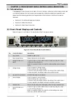
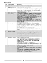
Page 31: ...ary Encoder adjusting the output voltage and navigating menu Button An auxiliary function to accept the voltage setting value in Preview mode 4 Voltage Display 4 digit 16 segment Voltage display Normally displays the output voltage In Preview mode the display indicates the setting of the output voltage In Menu navigation the display indicates the selected function 5 Operation Mode Indicator CV CC ...

Page 32: ...ce control Analog Programming Monitoring range selection Internal Resistance function Constant power limit function and Slew Rate control function Green LED lights when the Configuration menu is active If Configuration menu is active press the CONF button to exit to the main menu 13 PROT Button Indicator Activates the Protection menu The Protection menu provides OVP setting UVL setting UVP functio...

Page 33: ...ypress for 15 seconds the display returns back to show actual output Voltage and Current Green LED lights when PREV mode is active 17 OUT Button Indicator Output ON OFF control Press OUTPUT to set the output ON or OFF Green LED lights when DC Output is enabled Red LED blinks in case of an alarm Refer to User Manual Alarms and Protective Functions section Table 2 1 Front Panel Controls and Indicato...

Page 34: ...ent Identifier 3 Power LED Power Supply ON OFF status LED Green LED lights when Power Supply is ON Power Switch ON 4 REM LED REMOTE status LED Green LED lights if power supply is controlled by a remote communication RS232 485 USB LAN OPTional 5 OUT LED Output ON OFF status LED Green LED lights when DC Output is enabled Red LED blinks in case of an alarm Refer to User Manual Alarms and Protective F...

Page 35: ...1 1 8 Serial In connector RJ 45 type connector used for connecting power supplies to RS232 or RS485 port of a computer for remote control purposes When using several power supplies in a power system the first unit Serial In is connected to the computer and the remaining units are chained Remote Out to Remote In Connector type Molex 95540 2881 9 Serial Out connector RJ 45 type connector used for ch...

Page 36: ...e output when using a power supply with an output greater than 60VDC Use wires with minimum insulation rating equivalent to the maximum output voltage of the power supply WARNUNG Bei Einsatz einer Stromversorgung mit einer Ausgangsspannung von über 60VDC besteht die Gefahr eines elektrischen Schlags Verwenden Sie nur Leitungen mit Isolationsklassen die mindestens für die maximale Ausgangsspannung ...

Page 37: ... 1 Power Supplies Outline Standard Unit Front View Blank Panel Unit Front View Standard Blank Panel Units Rear View Standard Blank Panel Units Side View Dimensions are in mm Bus bar Detail Note 1 Note 2 Note 5 Note 4 Note 3 ...

Page 38: ...ied with power supply 5 Isolated control and signals connector Mating plug supplied with power supply 6 AC cable strain relief LAPP GROUP P N 5301 5420 supplied with the power supply 7 Output enclosure for models up to 100VDC output supplied with the power supply 8 AC input rating and safety approval symbols are shown here according to the specifications Strain Relief tolerance is dependent on the...

Page 39: ...This chapter contains instructions for initial inspection preparation for use and repackaging for shipment Connection to PC setting the communication port and linking power supplies are described in the User manual NOTE power supplies generate magnetic fields which might affect the operation of other instruments If your equipment is susceptible to magnetic fields do not position it adjacent to the...

Page 40: ...supply to the AC source Section 4 7 4 Test Turn on checkout procedure Section 4 8 5 Load connection Wire size selection Local Remote sensing Single or multiple loads Section 4 9 6 Default setting The power supply setting at shipment User Manual Table 4 1 Basic Setup Procedure 4 3 Initial Inspection Prior to shipment this power supply was inspected and found free of mechanical or electrical defects...

Page 41: ...ion Blank panel used only for single unit installation Right and left fixing brackets Handles 2 Pcs Flat head screws M3X6 6Pcs Flat head screws M3X8 6Pcs Flat head screws M3X10 3Pcs Flat head screws M4X8 4Pcs SEMS screws M3X8 5Pcs HEX Nut M3 3Pcs Flat washer M3 3Pcs Spring washer M3 3Pcs 4 4 2 Single Unit Installation In a single unit rack mount assembly the unit can be assembled on the left half ...

Page 42: ...the blank panel as shown in Figure 4 2 Figure 4 2 Left corner assembly to Blank Panel 2 Fix handle to the right corner then fix the right corner to the power supply as shown in Figure 4 3 3 Fix the right fixing bracket to the power supply as shown in Figure 4 3 Adjust the location of the fixing bracket to fit the depth of the cabinet Figure 4 3 Right corner and fixing bracket assembly to power sup...

Page 43: ...e unit Such damage is not covered under manufacturer s warranty General note All M3 screws tightening torque is 4 7 5 7 Lbf inch 0 53 0 64Nm All M4 screws tightening torque is 12 5 13 5 Lbf inch 1 41 1 52Nm 1 Insert the connection bracket to the rectangular holes in the right wall of the left half side power supply 2 Push the connection bracket toward the rear side of the power supply and then fix...

Page 44: ...assembly 4 Assemble the right half side unit to connection bracket as shown in Figure 4 8 Figure 4 8 Assembly 5 Push the left half side unit forward while holding the right half side unit still 6 Tighten the ground screw previously unscrewed sems screw M3X8 back to the rear panel through the hole in the connection bracket as shown In Figure 4 9 Figure 4 9 Assembly lock ...

Page 45: ...d handles to the front side of the units and the left and right fixing brackets to the side of the units as shown in Figure 4 10 Figure 4 10 Assembly completion 4 4 4 GH RM Rack Mounting Outline Drawings Figure 4 11 GH RM Rack mount outline ...

Page 46: ...4U 4 5 1 GH MO Option Kit GH MO 2U 2U plates 2Pcs SEMS screw M3X8 4Pcs GH MO 3U 3U plates 2Pcs SEMS screw M3X8 6Pcs GH MO 4U 4U plates 2Pcs SEMS screw M3X8 8Pcs 4 5 2 GH MO Installation General note All screws tightening torque is 4 7 5 7 Lbf inch 0 53 0 64Nm Stack the units on each other and fix the connection plates as shown in Figure 4 12 Figure 4 12 GH MO Assembly ...

Page 47: ...a where the ambient temperature does not exceed 50 C Refer to product Spec for operating conditions VORSICHT Halten Sie vor und hinter dem Gerät einen lichten Mindestabstand von 10 cm ein Das Netzgerät sollte nur in Arbeitsbereichen benutzt werden in denen die Umgebungstemperatur 50 C nicht übersteigt siehe Produktspezifikationen für Betriebsbedingungen 4 6 1 Foot Snaps Assembly In the accessories...

Page 48: ...s an wenn der Berührungsschutz nicht ordnungsgemäß angebracht wurde CAUTION Connection of this power supply to an AC source should be made by an electrician or other qualified personnel VORSICHT Nur Elektriker oder anderes Fachpersonal sollten dieses Netzgerät an die Wechselstromquelle anschließen CAUTION There is a potential shock hazard if the power supply chassis with cover in place is not conn...

Page 49: ...rrule with without plastic sleeve It is forbidden to solder the conductors The solder tin yields and fractures under high pressure The result is an increased contact resistance and an excessive temperature rise In addition corrosion caused by pickling or fluxes has been observed on soldered conductor ends Notch fractures at the transition point from the rigid to the flexible conductor area are als...

Page 50: ...ist usw sollen in der endgültigen System Installation vorhanden sein Diese Trennvorrichtung sollte alle Versorgungsleitungen gleichzeitig unterbrechen und muss für das Service Personal einfach zugänglich sein 4 7 1 AC Input Connector 1 Ensure that the AC cable is disconnected from any electrical potential before making any connection to the power supply The AC input connector is a header refer to ...

Page 51: ...n the accessories box from the inside part of the bracket by using manual force only Figure 4 14 Insertion of the Plastic Nut into Strain Relief Bracket 4 Unscrew the conical cable entry part until it is possible to insert the AC cable 5 Insert the AC cable through the conic cable gland entry and the strain relief bracket as shown in Figure 4 15 4 wires are shown it applies to 1 Phase 3 wires as w...

Page 52: ...Fix the strain relief release assembly to the rear panel with two M3x8 Sems screws as shown in Figure 4 17 The Sems screws are supplied in the accessories kit Tightening torque 4 7 5 7 Lbf inch 0 53 0 64Nm Figure 4 17 Strain Relief Assembled to Power Supply Rear Panel 9 Close by manual force the cable gland conic entry part until the AC cable is tightened Beware not to apply excessive force ...

Page 53: ... 8 2 Prior to Operation 1 Ensure that the power supply is configured to the default setting refer to User Manual IA761 04 02_ Parameter Setting Memory section 2 Power On Off switch at Off position 3 Ensure that the protection of output terminals is mounted and properly assembled 4 Connect the unit to an AC source as described in Section 4 7 5 Connect a DVM with appropriate cables for the rated vol...

Page 54: ...rent Check Standard Power Supply 1 Ensure that the front panel Power switch is at Off position and the DVM connected to the output terminals shows zero voltage 2 Connect a DC shunt across the output terminals 3 Ensure that the shunt and the wires current ratings are higher than the power supply rating 4 Connect a DVM to the shunt 5 Turn the front panel Power switch to On position 6 Turn on the out...

Page 55: ... Turn the front panel Power switch to On position 7 Run terminal communication software and send the following commands to turn power supply output ON INST NSEL 6 OUTP 1 Remember to use Carriage Return after each command 8 Ensure that the output current readback varies while sending CURR YY command The control range is from zero to the maximum rated output for the power supply model Send MEAS CURR...

Page 56: ... Sie Spannung anlegen 4 9 1 Load Wiring The following considerations should be made to select wiring for connecting the load to the power supply Current carrying capacity of the wire refer to Section 4 9 2 Insulation rating of the wire should be at least equivalent to the maximum output voltage of the power supply Maximum wire length and voltage drop refer to Section 4 9 2 Noise and impedance effe...

Page 57: ...ires insulation should fit into the specifications in Figure 4 18 Figure 4 18 Bus bar Cover Wire Diameter Limitation 4 9 4 Wire Termination The wires should be properly terminated with terminals securely attached DO NOT use non terminated wires for load connection at the power supply 4 9 5 Noise and Impedance Effects To minimize the noise pickup or radiation the load wires and remote sense wires s...

Page 58: ... output voltage of the power supply Ensure that the protection of output Connector Bus bars is properly assembled WARNUNG An den Ausgängen und den Ladungsanschlüssen kann gefährliche Spannung anliegen wenn ein Netzgerät mit einer Nennleistung von mehr als 60V benutzt wird Vergewissern Sie sich dass es an der Last und ihren Anschlüssen keine berührbaren spannungsführenden Teile gibt um das Personal...

Page 59: ...than specified in the specifications VORSICHT Es ist sehr wichtig bei hohen Stromabgaben die Ausgangsanschlüsse ordnungsgemäß herzustellen und die Anweisungen zu befolgen Unsachgemäße Anschlüsse können zu einem übermäßigen Temperaturanstieg führen oder der Grund dafür sein dass das Netzgerät in den Schutzmodus schaltet wenn der Spannungsabfall auf den stromführenden Leitern die Spezifikationen übe...

Page 60: ...hazard when using a power supply with an output voltage greater than 60VDC Do not turn ON power supply without output plug protection assembled Ensure that the protection of output plug is mounted and properly assembled WARNUNG Bei Einsatz eines Netzgeräts mit mehr als 60VDC Nennspannung besteht das Risiko eines Stromschlags Schalten Sie kein Netzgerät wenn die Schutzabdeckung des Ausgangssteckers...

Page 61: ...Leiterenden von Beiz oder Flussmitteln verursachter Rost beobachtet Kerbenbrüche am Übergangspunkt vom starren zum flexiblen Leiterbereich sind ebenfalls möglich The 150V to 600V models have four terminal wire clamp output connector The two left terminals are positive outputs and the other two right terminals are the negative outputs The connector requirements are as follows Connector type GIC 2 5...

Page 62: ...load to ground it is recommended to ground the output terminal as close as possible to the power supply chassis ground Always use two wires to connect the load to the power supply regardless of how the system is grounded NOTE When grounding output terminals as a part of series connection several precautions must be taken into consideration Refer to the User manual IA761 04 02_ Series Operation sec...

Page 63: ...le Nennisolierung besitzen die größer als die maximale Ausgangsspannung des Netzgeräts ist oder ihr entspricht Vergewissern Sie sich dass die Anschlüsse am Ladungsende geschützt sind um versehentlichen Kontakt mit gefährlichen Spannungen zu verhindern 4 10 2 Local Sensing The power supply is shipped with unconnected J8 sense connector In this configuration the unit is sensing the output voltage at...

Page 64: ...a front panel or communication 4 Turn On the power supply NOTE In order to ensure correct operation in remote sense mode ensure that the voltage drop on the sensing wires meets product specifications 4 10 4 J8 Sense Connector Technical Information J8 connector type SPT THR 1 5 3 H 3 5 P26 Phoenix contact Wire AWG 24 up to 18 Wire type Solid Flexible conductor or conductor with ferrule without plas...

Page 65: ...PM O C from rated output current following 30 minutes warm up 150V 600V models 70PPM O C from rated output current following 30 minutes warm up 5 Temperature stability 0 01 of rated Iout over 8hrs interval following 30 minutes warm up Constant line load temperature 6 Warm up drift 10V 100V models Less than 0 25 of rated output current over 30 minutes following power on 150V 600V models Less than 0...

Page 66: ... 661 5 4 Over voltage programming accuracy 1 of rated output voltage 5 Output under voltage limit UVL Prevents from adjusting Vout below limit Does not apply in analog programming Preset by front panel or communication port 6 Over temperature protection Shuts down the output Auto recovery by autostart mode 7 Output under voltage protection UVP Prevents adjustment of Vout below limit P S output tur...

Page 67: ...aranteed to maximum 0 2 of rated output current 3 For cases where conformance to various safety standards UL IEC etc is required to be described as 100 240Vac 50 60Hz 4 Signal and control ports interface cables length Less than 3m DC output power port cables length Less than 30m 5 Not including EMI filter inrush current less than 0 2mS 6 85 132Vac or 170 265Vac Constant load 7 From No Load to Full...

Page 68: ...64 This page intentionally left blank ...

Page 69: ..._____ ________________________________________________ ________________________________________________ ________________________________________________ ________________________________________________ ________________________________________________ ________________________________________________ ________________________________________________ ________________________________________________ __...

Page 70: ..._____ ________________________________________________ ________________________________________________ ________________________________________________ ________________________________________________ ________________________________________________ ________________________________________________ ________________________________________________ ________________________________________________ __...

Reviews: