39
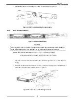
4. Fix the blank panel to the left side of the power supply as shown in Figure 4-4.
Figure 4-4: Blank panel assembly to power supply
4.4.3
Dual Unit Installation
Figure 4-5: Dual unit installation
CAUTION
Do not apply any stress on the units' front panel during assembly or disassembly. Stress on the front
panel may damage the unit. Such damage is not covered under manufacturer’s warranty.
General note: All M3 screws tightening torque is 4.7-5.7 Lbf-inch(0.53-0.64Nm).
All M4 screws tightening torque is 12.5-13.5 Lbf-inch(1.41-1.52Nm).
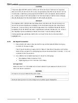
1. Insert the connection bracket to the rectangular holes in the right wall of the left half side power
supply.
2. Push the connection bracket toward the rear side of the power supply and then fix the bracket to
the chassis with 6 flat head screws as shown in Figure 4-6.
Figure 4-6: Connection bracket fixing to left unit


