61
CHAPTER 5:
SPECIFICATIONS
5.1
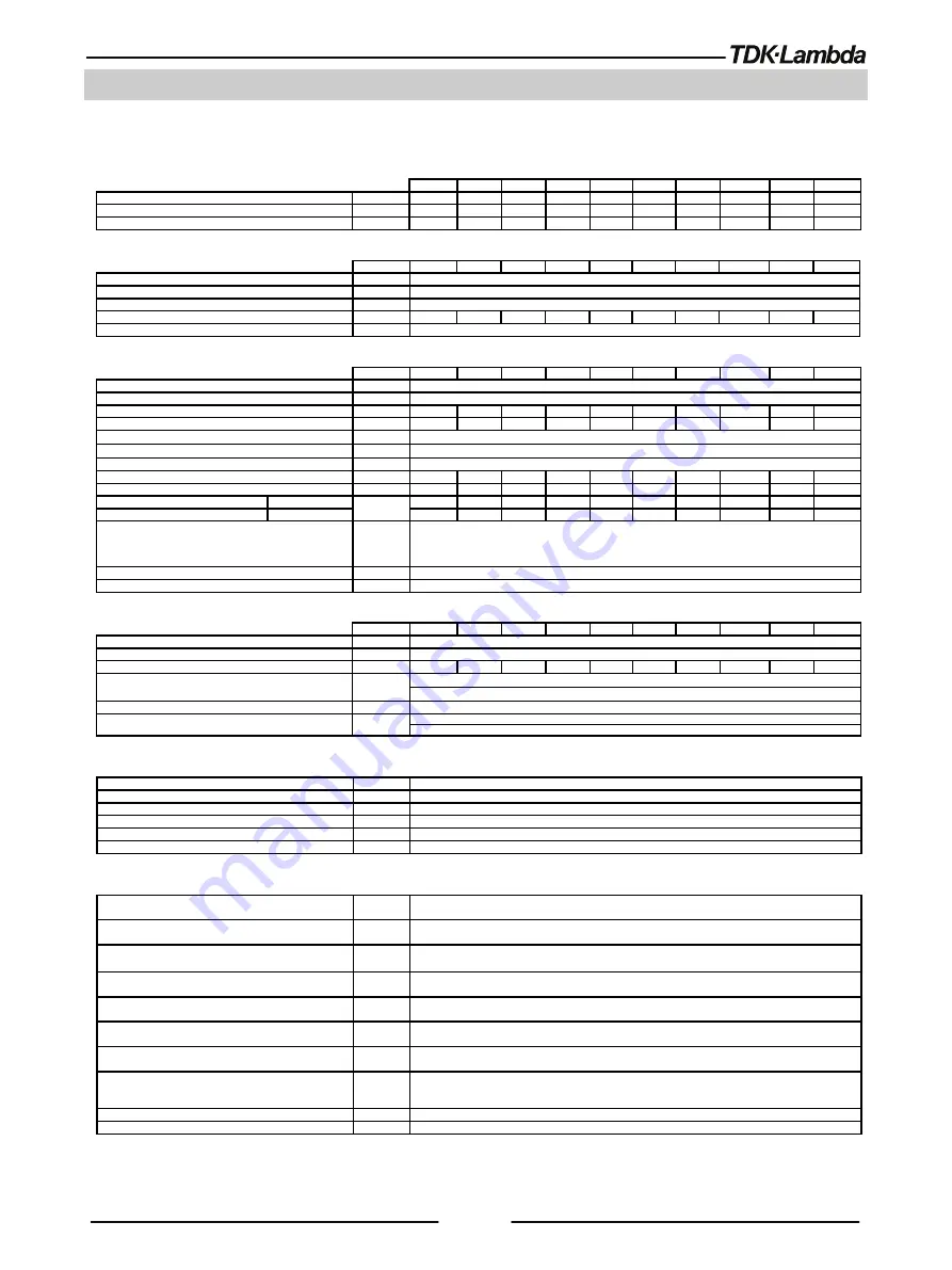
GH1.5kW Series Specifications
Unless otherwise noted, specifications are warranted over the ambient temperature range of 0° to 50° Celsius.
OUTPUT RATING
10-150
20-75
30-50
40-38
60-25
80-19
100-15
150-10
300-5
600-2.6
1.Rated output voltage (*1)
V
10
20
30
40
60
80
100
150
300
600
2.Rated output current (*2)
A
150
75
50
38
25
19
15
10
5
2.6
3.Rated output power at
100Vac≤Vin≤265Vac, Ta≤50
W
1500
1500
1500
1520
1500
1520
1500
1500
1500
1560
INPUT CHARACTERISTICS
V
10
20
30
40
60
80
100
150
300
600
1.Input voltage/freq. (*3)
---
85~265Vac continuous, 47~63Hz, single phase.
2.Maximum input current at 100% load (at 100Vac/200Vac)
A
18.5/9
3.Power Factor (Typ.)
---
0.99 @ 100Vac, 0.98 @ 200Vac, rated output power.
4.Efficiency (Typ. at 100Vac/200Vac)(*17)
%
86/88
87/89
87/89
87/89
87/89
87/89
88/90
88/90
88/90
88/90
5.Inrush current (*5)
---
Less than 50A.
CONSTANT VOLTAGE MODE
V
10
20
30
40
60
80
100
150
300
600
1.Max. Line regulation (*6)
---
0.01% of rated output voltage.
2.Max. Load regulation (*7)
---
0.01% of rated output v2mV.
3.Ripple and noise (p-p, 20MHz) (*8)
mV
50
50
50
60
60
75
130
75
180
500
4.Ripple r.m.s. 5Hz~1MHz (*8)
mV
6
6
6
7
7
8
30
20
45
100
5.Temperature coefficient
---
50PPM/
O
C from rated output voltage, following 30 minutes warm-up.
6.Temperature stability
---
0.01% of rated Vout over 8hrs interval following 30 minutes warm-up. Constant line, load & temperature.
7.Warm-up drift
---
Less than 0.01% of rated output v2mV over 30 minutes following power on.
8.Remote sense compensation/wire (*10)
V
2
2
5
5
5
5
5
5
5
5
9.Up-prog. response time (*11)
mS
20
20
20
20
20
20
20
30
30
40
10.Down-prog. response time (*12)
Full load
mS
20
20
20
30
30
50
50
60
70
80
No load
300
500
600
900
1200
1300
1700
2200
2700
3000
11.Transient response time
---
Time for output voltage to recover within 0.5% of its rated output for a load change 10~90% of rated
output current.
Output set point: 10~100%, Local sense.
Less than 1mS for models up to and including 100V. 2mS for models above 100V.
12.Start-up delay
---
Less than 6Sec.
13.Hold-up time
---
20mS Typical. Rated output power.
CONSTANT CURRENT MODE
V
10
20
30
40
60
80
100
150
300
600
1.Max. Line regulation (*6)
---
0.01% of rated output c2mA.
2.Max. Load regulation (*9)
---
0.02% of rated output c5mA.
3.Ripple r.m.s. (*13)
mA
≤250
≤
130
≤
100
≤
60
≤50
≤30
≤
40
≤
10
≤
8
≤
5
4.Temperature coefficient
---
10V~100V models: 100PPM/
O
C from rated output current, following 30 minutes warm-up.
150V~600V models: 70PPM/
O
C from rated output current, following 30 minutes warm-up.
5.Temperature stability
---
0.01% of rated Iout over 8hrs. interval following 30 minutes warm-up. Constant line, load & temperature.
6.Warm-up drift
---
10V~100V models: Less than +/-0.25% of rated output current over 30 minutes following power on.
150V~600V models: Less than +/-0.15% of rated output current over 30 minutes following power on.
ANALOG PROGRAMMING AND MONITORING (ISOLATED FROM THE OUTPUT)
1.Vout voltage programming
---
0~100%, 0~5V or 0~10V, user selectable. Accuracy and linearity: +/-0.15% of rated Vout.
2.Iout voltage programming (*14)
---
0~100%, 0~5V or 0~10V, user selectable. Accuracy and linearity: +/-0.4% of rated Iout.
3.Vout resistor programming
---
0~100%, 0~5/10K
Ω
full scale, user selectable. Accuracy and linearity: +/-0.5% of rated Vout.
4.Iout resistor programming (*14)
---
0~100%, 0~5/10K
Ω
full scale, user selectable. Accuracy and linearity: +/-0.5% of rated Iout.
5.Output voltage monitor
---
0~5V or 0~10V, user selectable. Accuracy: +/-0.5% of rated Vout.
6.Output current monitor (*14)
---
0~5V or 0~10V, user selectable. Accuracy: +/-0.5% of rated Iout.
SIGNALS AND CONTROLS (ISOLATED FROM THE OUTPUT)
1.Power supply OK #1 signal
---
Power supply output monitor. Open collector. Output On: On. Output Off: Off.
Maximum Voltage: 30V. Maximum Sink Current: 10mA.
2.CV/CC signal
---
CV/CC Monitor. Open collector. CC mode: On. CV mode: Off. Maximum Voltage: 30V.
Maximum Sink Current: 10mA.
3.LOCAL/REMOTE Analog control
---
Enable/Disable analog programming control by electrical signal or dry contact. Remote:
0~0.6V or short. Local: 2~30V or open.
4.LOCAL/REMOTE Analog signal
---
Analog programming control monitor signal. Open collector. Remote: On. Local: Off.
Maximum Voltage: 30V. Maximum Sink Current: 10mA.
5.ENABLE/DISABLE signal
---
Enable/Disable PS output by electrical signal or dry contact.
0~0.6V or short, 2~30V or open. User selectable logic.
6.INTERLOCK (ILC) control
---
Enable/Disable PS output by electrical signal or dry contact.
Output ON: 0~0.6V or short. Output OFF: 2~30V or open.
7.Programmed signals
---
Two open drain programmable signals. Maximum voltage 25V. Maximum sink current 100mA
(shunted by 27V zener).
8.TRIGGER IN / TRIGGER OUT signals
---
Maximum low level input voltage = 0.8V. Minimum high level input voltage = 2.5V.
Maximum high level input = 5V positive edge trigger: tw = 10us minimum. Tr,Tf = 1us maximum.
Min delay between 2 pulses 1ms.
9.DAISY_IN/SO control signal
---
By electrical Voltage: 0~0.6V/2~30V or dry contact.
10.DAISY_OUT/PS_OK #2 signal
---
4~5V = OK, 0V (500
Ω
impedance) = Fail.


