40
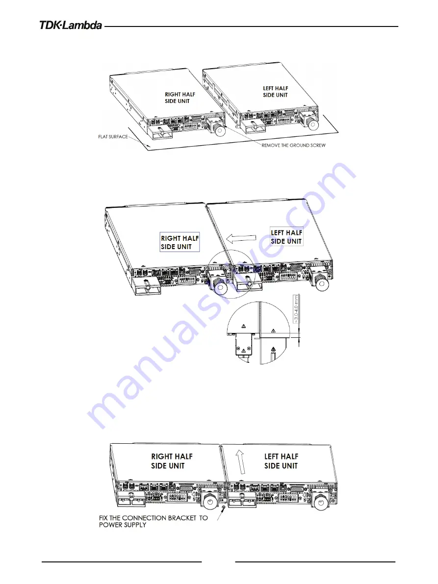
3. Place the two units side-by-side on a flat surface and remove the ground screw of the right half
side unit as shown in Figure 4-7.
Figure 4-7: Preparing the units for assembly
4. Assemble the right half side unit to connection bracket as shown in Figure 4-8.
Figure 4-8: Assembly
5. Push the left half side unit forward while holding the right half side unit still.
6. Tighten the ground screw previously unscrewed (sems screw M3X8), back to the rear panel
through the hole in the connection bracket as shown In Figure 4-9.
Figure 4-9: Assembly lock


