INSTRUCTION MANUAL
GXE600 Series
TDKLambda
<Page>
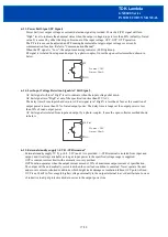
• Communication function (RS485)
Connect
“
+DATA
(
Pin No.19
)”
,
“
DATA
(
Pin No.20
)”
,
“
SG (Pin No.17)
”
to master unit. (Signal lines
shall be twisted.)
Connection of
“
SG (Pin No.17)
”
is optional. To prevent communication failure, the connection is
recommended.
Termination resistor is not built in. The connection of termination resistor at the master port and the farthest
slave port from the master unit is recommended.
• External standby supply (STB)
Connect
“
+STB
(
Pin No.14
)”
and
“
STB
(
Pin No.16
)”
to load.
(STB lines shall be twisted.)
12/28
Load
19
20
17
18
15
16
13
14
11
12
9
10
7
8
5
6
3
4
1
2
CN84
Master
unit
Termination
resistor
120
Ω
+D
A
T
A
-D
A
T
A
SG
Master
Signal ground
RS485 Bus twisted pair wire
+D
A
T
A
-D
A
T
A
SG
GXE #1
+D
A
T
A
-D
A
T
A
SG
GXE #2
+D
A
T
A
-D
A
T
A
SG
GXE #N
Termination
resistor
120
Ω
Load
+


