-10-
TDK-Lambda
HWS1000 Series
INSTRUCTION MANUAL
5. Functions and Precautions
5-1. Input Voltage Range
Input voltage range is single phase 85
-
265VAC (47
-
63Hz). Input voltage, which is out of specification, may
cause unit damage. Rated input voltage range fix during safety standard application is from100V to 240VAC (50/60Hz).
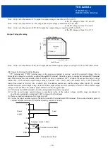
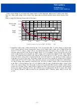
While applying input voltage from 85Vac to 90Vac, output load current derating is required.
5-2. Output Voltage Range
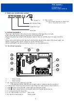
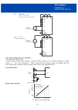
Output voltage is set to the rated value at shipping. V.ADJ trimmer on the front panel side is use to adjust the output
voltage within the range specified. Output voltage trimming range is within -20%
-
+20% of the rated output voltage
(48V, 60V model: -20%
-
+10%). Turn the trimmer clockwise to increase output voltage. Take note when the output
voltage is increased excessively over voltage protection (OVP) function may trigger and output voltage will shut down.
Use the output power of the power supply below the rated output power value when you raise the output voltage.
5-3. Over Voltage Protection (OVP)
The OVP function (Inverter shut down method, manual reset type) is provided. OVP function operates within
125-145% of the rated DC output voltage value (3-7V model: 125-140%, 36V model: 125-138%, 48V, 60V model:
115-125%), and the output will be shut down when OVP function triggers. When OVP function operates, the input power
is cut off for a few minutes, and then power is re-input or remote ON/OFF control signal shall be input for recovery of
the output. OVP value is fixed and can not be adjusted.
5-4. Over Current Protection (OCP)
The OCP function (Constant current limiting, Time delay shutdown type) is provided. OCP function operates when the
output current exceeds 105% of maximum DC output current specification and the over current or short circuit condition
continues 5-second or more, the output will be shut down. When the OCP is triggered, the input power is cut off for a
few minutes, and then power is re-input or remote ON/OFF control signal should be input for recovery of the output. The
OCP setting is fixed and not to be adjusted externally.
5-5. Over Temperature Protection (OTP)
Over temperature protection function (manual reset type) is provided. When ambient or internal temperature rises
abnormally, OTP will shut down the output. When OTP is triggered, input power is cut off and allow sufficient cooling to
reset the OTP function. Then power is re-input or remote ON/OFF control signal should be input for recovery of the
output.
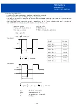
5-6. Low Output Detection Circuit (PF)
Low output voltage detection circuit is provided. Power Fail signal (PF signal) will output when output voltage
decrease by either the drop or brown out of the input voltage or OCP, OVP and OTP function operation. PF signal will
turn “High” level to indicate the abnormal status of the power supply when the output voltage decrease to 80% of the
output voltage setting value. However, there is a possibility that PF signal may not output during parallel operation. The
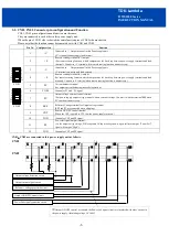
PF signal circuit is insulated from the power supply input and output circuit and it is an open collector. TOG terminal is
ground for PF terminal.
When the Built-in Fan Motor of this power supply unit stops, PF signal will turn to “H” and the output power will shut
down. The Built-in Fan Motor is a component with lifetime. We recommend a periodic replacement. Please contact our
sales office. Replacement is at customer’s expenses.
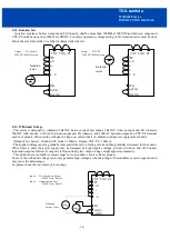
PF
TOG
Vce max
:
30V
Ic max
:
20mA


