


PAH300
・
350S24
-SERIES
TDK-Lambda
11
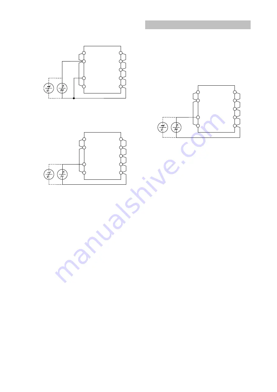
Withstand voltage Tester
+Vin
CASE
CNT
-Vin
+V
+S
TRM
-S
-V
1.5kVDC 1 minute (10mA)
Fig.19-1 Withstand Voltage Test for Input-Output
and Input-Baseplate
Withstand voltage Tester
+Vin
CASE
CNT
-Vin
+V
+S
TRM
-S
-V
500VDC 1minute (10mA)
Fig.19-2 Withstand Voltage Test for Output-Baseplate
20. Isolation Resistance
Use DC isolation tester (MAX 500V) between output
and baseplate. Isolation resistance value is 100M
Ω
and
above at 500VDC applied voltage. Also take note that
depending on the isolation tester used, some testers
generate high voltage pulse. Discharge the power module
after test using a resistor, etc.
DC Isolation Tester
+Vin
CASE
CNT
-Vin
+V
+S
TRM
-S
-V
Over 100M
Ω
at 500VDC
Fig.20-1 Isolation Test
21. Vibration
Vibration of power module is defined in case of
mounting on printed circuit board.
22. Shock
Withstand shock value is defined to be the value at
Densei -Lambda shipment and packaging conditions.
23. CE MARKING / UKCA MARKING
CE MARKING
CE Marking, when applied to a product or packing
material for a product covered by this handbook,
indicates compliance with the Low Voltage
Directive and RoHS Directive.
UKCA MARKING
UKCA Marking, when applied to a product or
packing material for a product covered by this
handbook, indicates compliance with the Electrical
Equipment (Safety) Regulations and Restriction of
the Use of Certain Hazardous Substances in
Electrical & Electronic Equipment Regulations.


