


PAH300
・
350S24
-SERIES
TDK-Lambda
6
●
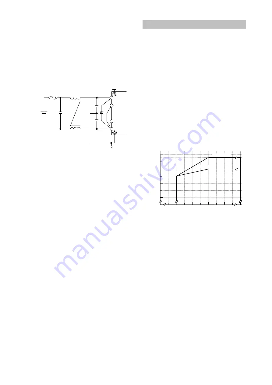
Recommended input filter as EMI countermeasure
(conforms to VCCI Class 1, FCC class A)
(1) Recommended input filter
as EMI countermeasure
CNT
+Vin
CASE
-Vin
C1
+
C7
C8
C9
Fuse
L1
POWER
MODULE
Fig.1-6 Recommended input filter
as EMI countermeasure
Recommended Values:
C1 : 680
μ
F (Electrolytic Capacitor)
3 pcs in parallel
C7 : 10
μ
F (Ceramic Capacitor)
C8,C9 : 0.47
μ
F (Film Capacitor)
L1 : 1mH (Common-mode choke coil)
Notes
1. For the power module output, connect output capacitors
described in the basic circuit connection.
2. C1 (Electrolytic Capacitor) value can be reduced if
impedance of input line is lower and operation of
power module is stable.
3. VCCI Class 1, FCC Class A limits can be satisfied
with the above recommended filter at Densei-Lambda
measuring conditions. However, there are cases where
above limits might not be satisfied due to input and
output wiring method, as well as, peripheral circuits.
When selecting input filter, be sure to verify actual
EMI characteristics (CE and RE) before finalizing the
filter. Refer to PAH300
・
350S24-* Evaluation Data for
details.
2. Output Voltage Adjustment Range
Output voltage could be adjusted within the range
described below by external resister or variable resistor.
However, take note that OVP might trigger when
output voltage adjustment exceeds the ranges indicated
below.
Output Voltage Adjustment Range
12V : -40%~+10% of nominal output Voltage
28V : -40%~+18% of nominal output Voltage
When increasing the output voltage, reduce the output
current accordingly so as not to exceed the maximum
output power.
Take note that input voltage range is limited as shown
in fig.2-1 when output voltage is increased.
Remote sensing is possible even when output voltage is
varied. For details on remote sensing function, please
refer to “9.Remote Sensing”.
Fig.2-1 Limit of Input Voltage
O
ut
pu
t V
ol
ta
ge
(%
)
36
18
18.5
19
19.5
110
100
90
Input Voltage (VDC)
120
28V Model
12V Model
118
60
0


