27
83550001 Revision C
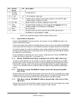
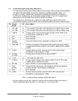
Pin
Signal
Name
I/O
Description
9
Analog
Ground
Analog ground
10
+10V
O
+10V reference, 2mA max
11
V-MON
O
Analog output voltage monitor signal, scaled 0-10V=0-100% rated
voltage. Series resistance is 10k
12
HV ON
I
Open=HV OFF, Connect to digital ground=HV ON
13
POL-
Status
O
Output Polarity indicator for units equipped with
optional
electronic
polarity reversal. +12V=Positive, 0V=Negative.
14
N/C
Not connected
15
I-SET
I
Output current set point, scaled 0-10V=0-100% rated current.
Resistance to ground approx. 10M
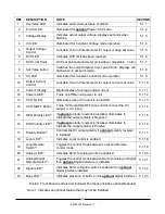
Table 5. Non-Isolated Analog Interface Signals (ANA option)
7.1.1.
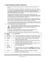
Typical Remote Operation
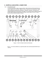
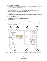
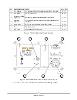
Set the LOCAL/REMOTE switch (see Item 18 in Figure 2) to the REMOTE position, the
LOCAL LED will extinguish.
If the power supply also features a Digital interface option, then set the DIGI TAL/ANALOG
switch (see Item 20 in Figure 2) to the ANALOG position, the ANALOG LED will illuminate.
The power supply can now be controlled via the analog interface (see Item 4 in Figure 2),
with the output voltage and current levels set by 0-10V signals, and HV ON/OFF function
by switches or relay contacts.
Some examples for operating the unit in various combinations of LOCAL and REMOTE
modes are shown in sections 7.1.2 through 7.1.4.
7.1.2.
Remote HV ON/OFF with LOCAL voltage/current controls (ANA option only)
Connect a switch between Pin 12 and Pin 6 to turn HV ON/OFF (closed=ON, open=OFF).
Hard wire Pin 5 to Pin 15 and Pin 4 to Pin 8. This setup allows the HV Output to be turned
ON and OFF remotely, but the front panel potentiometers still set the output voltage and
current. This connection will only work with the non-isolated analog interface option (ANA
option).
7.1.3.
HV Output is always ON, REMOTE Voltage and Current programming (ANA
option only)
Hard wire Pin 12 and 6 to turn ON the output. Connect 0-10V to Pin 8 to program the output
voltage, and 0-10V to Pin 15 to program the output current. The internal 10V reference (Pin
10) can be used with external potentiometers to generate the program signals.
7.1.4.
HV Output is always ON, REMOTE Voltage programming, Current set to 100%
rated value
Hard wire Pin 12 and 6 to turn ON the output. Connect 0-10V to Pin 8 to program the output
voltage. Hard wire Pin 15 to Pin 10 to set the current to 100% of rated.
Summary of Contents for PHV Series
Page 11: ...8 83550001 Revision C 2 SPECIFICATION...
Page 12: ...9 83550001 Revision C Mechanical Details...
Page 14: ...11 83550001 Revision C This Page Left Intentionally Blank...
Page 26: ...23 83550001 Revision C This Page Left Intentionally Blank...
Page 32: ...29 83550001 Revision C This Page Left Intentionally Blank...
Page 34: ...31 83550001 Revision C This Page Left Intentionally Blank...
Page 36: ...33 83550001 Revision C This Page Left Intentionally Blank...
Page 37: ...34 83550001 Revision C Notes...

