AN-000158
Document Number: AN-000158
Page 10 of 22
Revision: 1.2
DEFINITION OF FIELD-OF-VIEW
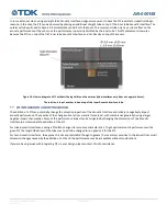
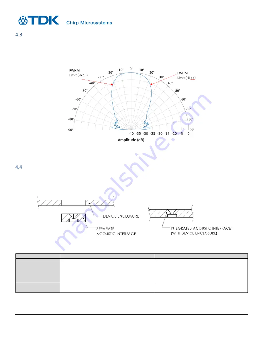
The FoV of the CH101 and ICU-10201 can be set to meet the application requirements by designing the appropriate Acoustic
Interface. It should be noted that, unlike the FoV of IR sensors, it is still possible to detect objects beyond the acoustic FoV. This is
because the acoustic FoV is defined as the full-width half-maximum (FWHM) of the round-trip beam pattern. If the reflected echo off
an object outside the FoV has an amplitude greater than the minimum amplitude threshold, it is still possible to detect such targets.
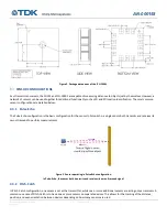
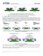
Figure 6. A beam pattern of a 45-degree FoV horn measured against a large flat target.
Note how the amplitude does not fall abruptly to zero (absolute units) and that depending on the target and the distance, it will still be possible
to detect targets outside the rated FoV.
SEPARATE VS INTEGRATED ACOUSTIC INTERFACE
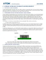
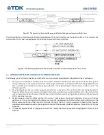
The Acoustic Interface can either be a standalone, separate part or it can be integrated into the device enclosure. The choice
between a separate or integrated Acoustic Interface depends on many factors. Some major tradeoffs of each approach are
highlighted in the table below.
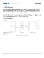
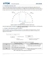
Figure 7. Separate Acoustic Interface (left) and integrated Acoustic Interface (right).
Separate Acoustic Interface
Integrated Acoustic Interface
Pros
•
More control over critical Acoustic Interface
dimensions and surfaces, which may lead to more
consistent results
•
Easier to ensure good and consistent contact with
sensor. Recommended for pitch-catch applications.
•
Removes potential gaps/flushness issues caused by
assembly variation. This is especially beneficial for
wide or omnidirectional FoV Acoustic Interfaces.
Cons
•
Requires at least one extra part in the BOM and extra
assembly step(s) to assemble the device
•
May require tighter tolerances and/or more Design
for Assembly considerations
Table 3. Tradeoffs of separate and integrated Acoustic Interfaces.


