AN-000158
Document Number: AN-000158
Page 18 of 22
Revision: 1.2
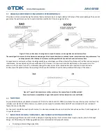
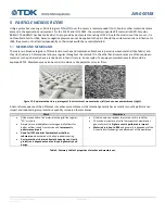
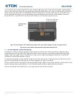
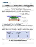
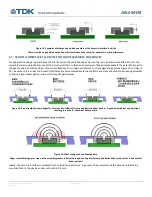
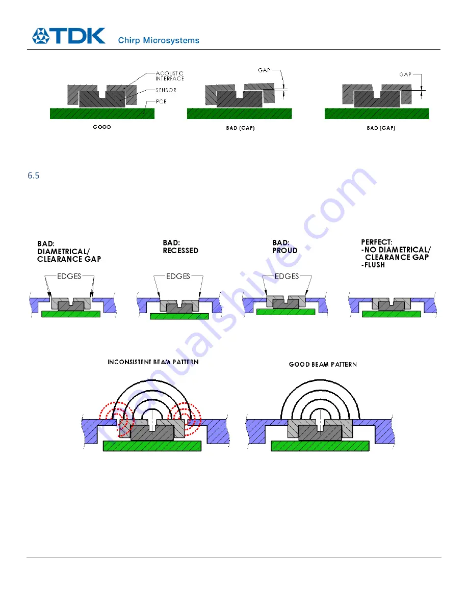
Figure 18. Examples of what good and bad assembly of the Acoustic Interface look like.
There must be no gap between the Acoustic Interface and the sensor for optimal acoustic performance.
ACOUSTIC INTERFACE-TO-DEVICE ENCLOSURE ASSEMBLY TOLERANCES
For applications using a separate Acoustic Interface from the overall device enclosure, there are additional considerations for the
assembly and associated tolerances of the Acoustic Interface to the device enclosure. They primarily address the potential impact to
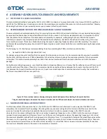
the beam pattern caused by obstructions and reflections from undesired features, such as edges and gaps (see Figure 19 and Figure
20 ). Because of this, wider FoV Acoustic Interfaces are more susceptible to these effects and steps should be taken during assembly
to ensure a good beam pattern and overall acoustic performance.
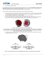
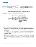
Figure 19. Bad assemblies create edges for ultrasound to reflect off from and affect the beam pattern. A good assembly has no gaps/steps,
resulting in a smooth, consistent beam pattern.
Figure 20. Effect of edges on the beam pattern.
Edges created from gaps or steps in the assembly process reflect ultrasound, causing interference (red dashed lines) and results in inconsistent
beam patterns.
Ideally, the Acoustic Interface is mounted flush to the device enclosure. In general, Chirp recommends the Acoustic Interface be
mounted flush to the device enclosure to within 0.2 mm.

