AN-000158
Document Number: AN-000158
Page 19 of 22
Revision: 1.2
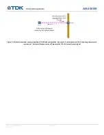
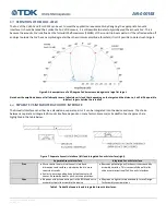
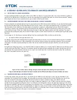
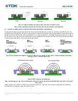
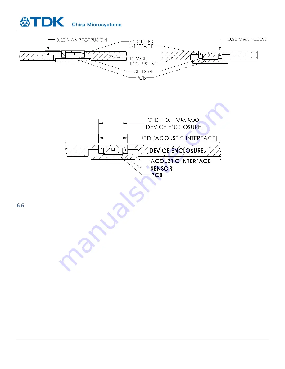
Figure 21. The Acoustic Interface should be mounted flush to the device enclosure to within 0.2 mm.
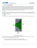
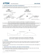
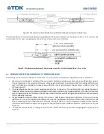
There should also be minimal diametrical/clearance gap between the Acoustic Interface and the device enclosure. Chirp recommends
no more than 0.1 mm clearance gap between the device enclosure and Acoustic interface.
Figure 22. The clearance gap between the device enclosure and Acoustic Interface should be 0.1 mm or less.
ASSEMBLY INSPECTION AND QUALITY CONTROL CHECKLIST
The following is a list of items to check to ensure that the sensor is correctly assembled and integrated into the overall device:
1.
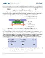
Sensor port is not blocked or occluded. If the sensor port is blocked or occluded, whether by the Acoustic Interface, glue or
foreign contaminants, the acoustic performance will be negatively affected. One simple method for checking that the sensor
port is not blocked or occluded is to visually inspect that the annular gold plating on the port hole is visible and is not
“
cut
off
”
2.
The assembly process does not impart
excessive residual stress on the sensor. This can be verified by checking the sensor’s
frequency before the sensor is securely attached to the Acoustic Interface (e.g. Acoustic Interface sits on top of the sensor
with only gravity) and after the sensor is fixed to the Acoustic Interface (such as with glue). Residual stress on the sensor will
shift its operating frequency.
3.
No gap between Acoustic Interface and top of the sensor. Gaps between the Acoustic Interface and sensor will reduce
performance. This can be (indirectly) checked by measuring the gap between the bottom of the Acoustic Interface and the
PCB or measuring the top of the Acoustic Interface to the top of the PCB. It is also important to check that the Acoustic
Interface is not mounted crooked or at an angle by checking that the Acoustic Interface top/bottom is parallel to the PCB (see
Figure 18).
4.
If a separate Acoustic Interface is being used, check that it meets the assembly requirements highlighted in Figure 21 and
Figure 22.

