AN-000158
Document Number: AN-000158
Page 17 of 22
Revision: 1.2
Sensor Configuration
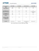
Max Assembly Force (grams-force)
Max Allowable Frequency Shift Due to
Assembly (Hz)
Pulse-Catch
50
750
Pitch-Echo
150
1500
Table 6. Summary of maximum allowable residual assembly force.
The easiest way to detect when this force is exceeded is to measure the frequency shift from before and after assembly.
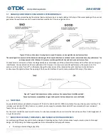
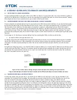
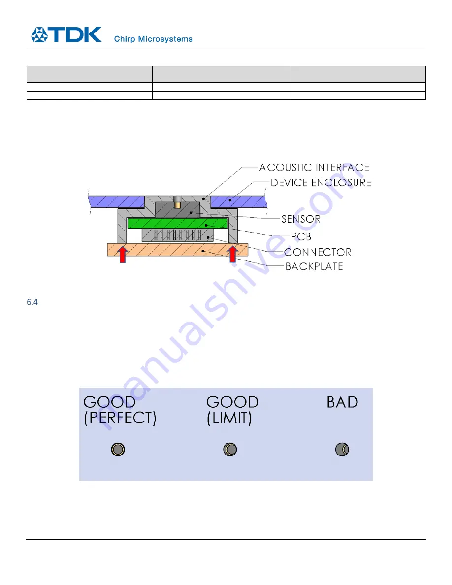
One method of holding the module against the device enclosure while avoiding applying excessive force on the module is to use a
backplate to transfer the force applied to the module to the Acoustic Interface instead of the sensor (see Figure 16).
Figure 16. Example of a backplate-based module design to avoid applying excessive force on the sensor.
SENSOR-TO-ACOUSTIC INTERFACE ASSEMBLY TOLERANCES
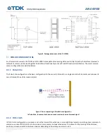
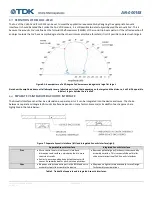
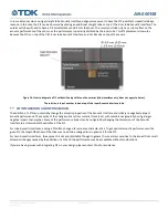
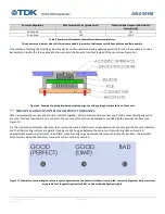
When assembling the sensor and Acoustic Interface together, Chirp recommends the sensor port hole be concentrically aligned to
Acoustic Interface to within 0.1 mm or better. The sensor port should not be blocked or occluded by the Acoustic Interface (see
Figure 17).
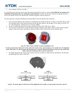
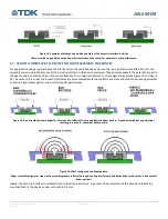
For the Z-dimension assembly tolerance, the only requirement is that there is no gap between the sensor and the Acoustic Interface
and that their mating surfaces are parallel (see Figure 18). Any gap between the sensor and Acoustic Interface will result in
unpredictable acoustic performance. In addition, while ensuring no gap between the sensor and Acoustic Interface, the assembly
force must be below the maximum force limit as discussed in Section 6.3.
Figure 17. Examples of various degrees of sensor port alignment with the Acoustic Interface, from perfect concentric alignment (left), maximum
acceptable limit tangent alignment (middle), to bad occluded alignment (right).

