AN-000158
Document Number: AN-000158
Page 8 of 22
Revision: 1.2
4
ACOUSTIC INTERFACES
The CH101 or ICU-10201 without an Acoustic Interface has poor sound output performance. The reason for this is the large acoustic
impedance difference between the PMUT (the source) and the air (the load) resulting in the energy from the PMUT not being
transferred efficiently to the air. In this regard, acoustic impedance can be thought of as analogous to electrical impedance. To
improve the transfer of sound energy to the air, an Acoustic Interface is required in front of the
sensor’s
port hole to better match
the impedance. In addition, the dimensions and geometry of the Acoustic Interface dictate the FoV of the sensor. Two broad
categories of Acoustic Interface are used with the CH101 and ICU-10201: tubes and horns.
TUBES
Tubes are holes of a specific length and diameter. For the CH101, the optimal tube length is 0.475 mm with a diameter of 0.7 mm. A
straight tube is the Acoustic Interface of choice for applications that require the smallest opening possible.
Straight tubes are always
omnidirectional
(~180 degree FoV).
HORNS
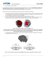
An acoustic horn focuses the acoustic beam, making the FoV narrower. The terminology used to describe horns is shown in Figure 5.
Figure 5. Terminology for acoustic horns.
The process of calculating and determining the required dimensions for different horns is complex and beyond the scope of this
document. However, in general, the following statements hold true.
•
The larger the mouth of the horn, the smaller the FoV, everything else being equal
•
The longer the horn (up to a limit), the higher the output pressure, everything else being equal


