SW-000103
Document Number: SW-000103
Page 30 of 51
Revision: 1.1
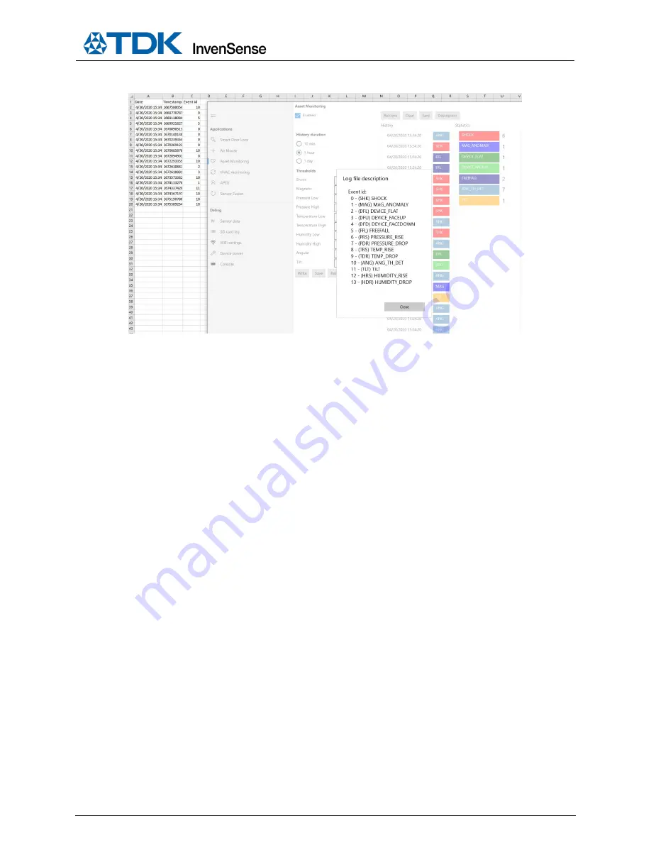
5.
Click the
Save
button to save events to the
am_history.csv
file.
Page 1: ...ecifications as may be required to permit improvements in the design of its products InvenSense Inc 1745 Technology Drive San Jose CA 95110 U S A 1 408 988 7339 www invensense com Document Number SW 0...
Page 2: ...nection 10 WiFi Connection 12 4 Sensor Data Mode 19 5 Smart Door Lock 25 6 Asset Monitoring 27 7 HVAC Monitoring 31 8 Sensor Fusion 33 9 Air Mouse 34 10 SD Card Logging Through the App 35 11 Standalon...
Page 3: ...SW 000103 Document Number SW 000103 Page 3 of 51 Revision 1 1 1 SMARTBUG MODULE Figure 1 SmartBug Module...
Page 4: ...SW 000103 Document Number SW 000103 Page 4 of 51 Revision 1 1 2 INSTALLING AND RUNNING SMARTBUG APP 1 Go to the Microsoft App Store and search for SmartBug...
Page 5: ...SW 000103 Document Number SW 000103 Page 5 of 51 Revision 1 1 2 Click on Install...
Page 6: ...Document Number SW 000103 Page 6 of 51 Revision 1 1 3 Go to the Type here to search Window and type Smart Then select the SmartBug to run the SmartBug app It can also be pinned to the taskbar for qui...
Page 7: ...e LED is blinking red more charging is needed If the LED is blinking blue it is charged enough and it is now advertising for a BLE connection with the SmartBug App Step 3 IF BLE is not connected to th...
Page 8: ...SW 000103 Document Number SW 000103 Page 8 of 51 Revision 1 1 3 Select one of three options BLE USB or WiFi Bluetooth Discovery Routine 1 Click on Search to discover the SmartBug module...
Page 9: ...the device and click OK When the BLE device is selected press the Connect button to connect the SmartBug module to the SmartBug App After clicking connect wait a few seconds until the Master device pa...
Page 10: ...the first time the app will ask to pair with it Click Yes The pairing is a secure BLE connection required by the Air mouse HID driver This ensures smooth functionality of the Air Mouse Application and...
Page 11: ...click OK When USB device is selected press the Connect button to connect the SmartBug module to the SmartBug App After clicking connect wait a few seconds until the Master device parameters appear If...
Page 12: ...ule after power down 1 Once the Add On board is connected in Power Down mode use the Power button on the Add On card to turn on the module in BLE mode 2 Once the Add On board is connected in Power Dow...
Page 13: ...nnect the BLE and initiate the WiFi connection to the specified router The BLE link status will change to Disconnected and the module s blue LEDs will turn off and the green LED on the Add On board wi...
Page 14: ...o go to the master device selection 2 Click on the WiFi option 3 Click on Retrieve local network parameters to populate the first and last IP Address sections for DHCP mode This button retrieves the a...
Page 15: ...SW 000103 Document Number SW 000103 Page 15 of 51 Revision 1 1...
Page 16: ...SW 000103 Document Number SW 000103 Page 16 of 51 Revision 1 1 5 Select the found device 6 Now it is ready for WiFi connection...
Page 17: ...WiFi can be disabled through the WiFi settings menu Such a transition occurs when a user unchecks the WiFi enabled checkbox and clicks on the Set button The WiFi connection will be lost and the blue...
Page 18: ...ble BLE again The BLE select master process is not required to connect to the same SmartBug board because its information is saved by the application A user can simply select the connection type BLE a...
Page 19: ...etometer temperature humidity ultrasonic and pressure sensors and record that data into log files It also provides tuning parameters to finetune the desired raw sensor data Note All the sensors except...
Page 20: ...SW 000103 Document Number SW 000103 Page 20 of 51 Revision 1 1 2 Select the sensor s by selecting the Enabled checkboxes Note You can stream and log data from all the sensors at the same time...
Page 21: ...SW 000103 Document Number SW 000103 Page 21 of 51 Revision 1 1 3 Enable data recording by selecting the Start recoding button...
Page 22: ...SW 000103 Document Number SW 000103 Page 22 of 51 Revision 1 1 4 After data has been recorded disable data recording by clicking on the Stop recording button...
Page 23: ...SW 000103 Document Number SW 000103 Page 23 of 51 Revision 1 1 5 Click Open log file to view recorded data with Microsoft Excel...
Page 24: ...s in log file 7 Maximum ODR supported on different interfaces for streaming and logging SENSOR ODR ACCEL GYRO MAG PRESSURE HUMIDITY TEMPERATURE ULTRASOUND ODR Options 25 50 100 200 1000 2000 10 50 100...
Page 25: ...n will automatically run upon clicking the Notifications checkbox The calibration can be re run at any time by clicking the Restart calibration button 2 Place the device on a door Please make sure tha...
Page 26: ...ate change 5 Log Smart Door Lock outputs with Angle The log file will record all door open and close events along with the door angle When the angle is enabled by the Enable Angle checkbox the SmartBu...
Page 27: ...SW 000103 Document Number SW 000103 Page 27 of 51 Revision 1 1 6 ASSET MONITORING 1 Select the Enabled checkbox to enable the Asset Monitoring SmartBug feature...
Page 28: ...values need to be configured and new values can be entered The new values can be saved in the configuration file with the Save button and then restored from the configuration by the Restore button in...
Page 29: ...to be monitored Start performing Asset Monitoring activities shock fall environment changes with the SmartBug device The SmartBug device will now capture events 4 Click the Retrieve button to load the...
Page 30: ...SW 000103 Document Number SW 000103 Page 30 of 51 Revision 1 1 5 Click the Save button to save events to the am_history csv file...
Page 31: ...the Enabled checkbox to enable HVAC 3 Place the two modules with a pressure sensor each on two sides of any air filter 4 Click the Calibrate now button to calibrate the master and slave pressure sens...
Page 32: ...ssure change and filter replacement notification Once the pressure difference exceeds a threshold the filter replacement notification is recorded This picture shows that the second notification has be...
Page 33: ...elected by choosing the 6 9 axis 3 Calibrate the magnetometer by performing a figure 8 motion with the SmartBug device to ensure proper 9 axis calibration 4 Click on the Set button 5 Start rotating th...
Page 34: ...lect the Air Mouse window and click the Enabled checkbox to enable the Air Mouse demonstration The PC mouse cursor will follow the motion of the SmartBug In order to disable the Air Mouse uncheck the...
Page 35: ...log events that can be enabled by clicking on the checkboxes 1 Click on the Start button to start logging The logging can be finished by the clicking Stop button Note The SD card should be on a FAT32...
Page 36: ...You can start the SD Card logging by pushing the SW2000 button for 2 seconds LED 1 on the Add On Board will start to blink every 3 seconds 6 You can tag an event by pushing the SW2000 button 7 When yo...
Page 37: ...ers The format is GYRO ENABLE DISABLE ODR FSR Gyro ODR in Hz can be set to 25 50 or 100 Gyro FSR 0 16dps 1 31dps 2 62dps 3 125dps 4 250dps 5 500dps 6 1000dps 7 2000dps ENABLE MAGNETOMETER LOG To enabl...
Page 38: ...You can change some parameters The format is PRES_TEMP ENABLE DISABLE ODR Pressure and Temperature ODR in Hz can be set to 1 5 or 10 ENABLE HUMIDITY AND TEMPERATURE LOG To enable the Humidity and Temp...
Page 39: ...change DISABLE to ENABLE You can change some parameters The format is APEX ENABLE DISABLE TAP_TMIN TAP_TMAX TAP_MIN_JERK_THR PED_STEP_CNT_TH PED_AMP_CNT_TH WOM_THR TAP_TMIN TAP_TMAX TAP_MIN_JERK_THR U...
Page 40: ...TH HUM_LOW_TH THUM_HIGH_TH ANG_TH TILT_TH Magnetic Threshold in nT Pressure Low Threshold in Pa Pressure High Threshold in Pa Temperature Low Threshold in C x10 Temperature High Threshold in C x10 Hum...
Page 41: ...1 1 ENABLE SENSOR FUSION LOG To enable the 3DOF Feature you must change the line starting with 3DOF and change DISABLE to ENABLE You can change some parameters The format is 3DOF ENABLE DISABLE MODE M...
Page 42: ...000103 Document Number SW 000103 Page 42 of 51 Revision 1 1 12 ACCESS SD CARD LOG In order to access SD card log connect SmartBug Module to PC with micro USB cable 1 Click on SD card log convert utili...
Page 43: ...00103 Page 43 of 51 Revision 1 1 The following window pops up 2 Browse to the log file on the SD Card drive and select it 3 Click on Export 4 After conversion is complete click on Open export folder t...
Page 44: ...768 1 g b Gyroscope Conversion from output to dps dps count FSR 32768 where Count count read from sensor FSR 16 32 64 125 250 500 1000 2000 selected by user Example Count 16384 FSR 2000 G 327 2000 327...
Page 45: ...red to connect the WiFi Add On board with the module Hot plugging should be avoided while the module is running There are two methods to turn on the module after power down 1 Once the Add On board is...
Page 46: ...firmware on the SmartBug device using the OTA firmware upgrade option This can be used to ensure that the latest version of firmware is loaded on the device 1 Disconnect the BLE connection 2 Click OT...
Page 47: ...SW 000103 Document Number SW 000103 Page 47 of 51 Revision 1 1 5 Click Yes on the pop up window to unpair DfuTarg from the device...
Page 48: ...Revision 1 1 6 Click Connect in the app 7 Click Yes again on the pop up window to pair SmartBug with your device The version of the firmware should now be upgraded and can be seen in the Master devic...
Page 49: ...w This can help with troubleshooting and debugging of the application The interface detailed messages can be enabled by the Debug file enabled check button In this case all communication messages will...
Page 50: ...SW 000103 Document Number SW 000103 Page 50 of 51 Revision 1 1 17 REVISION HISTORY REVISION DATE REVISION DESCRIPTION 03 08 2020 1 0 Initial Draft 07 15 2020 1 1 Updated for launch...
Page 51: ...al property rights Certain intellectual property owned by InvenSense and described in this document is patent protected No license is granted by implication or otherwise under any patent or patent rig...