12
V
ersa
s
afe
TM
I
nsTallaTIon
r
oute
P
oWer
and
C
ommuniCation
C
able
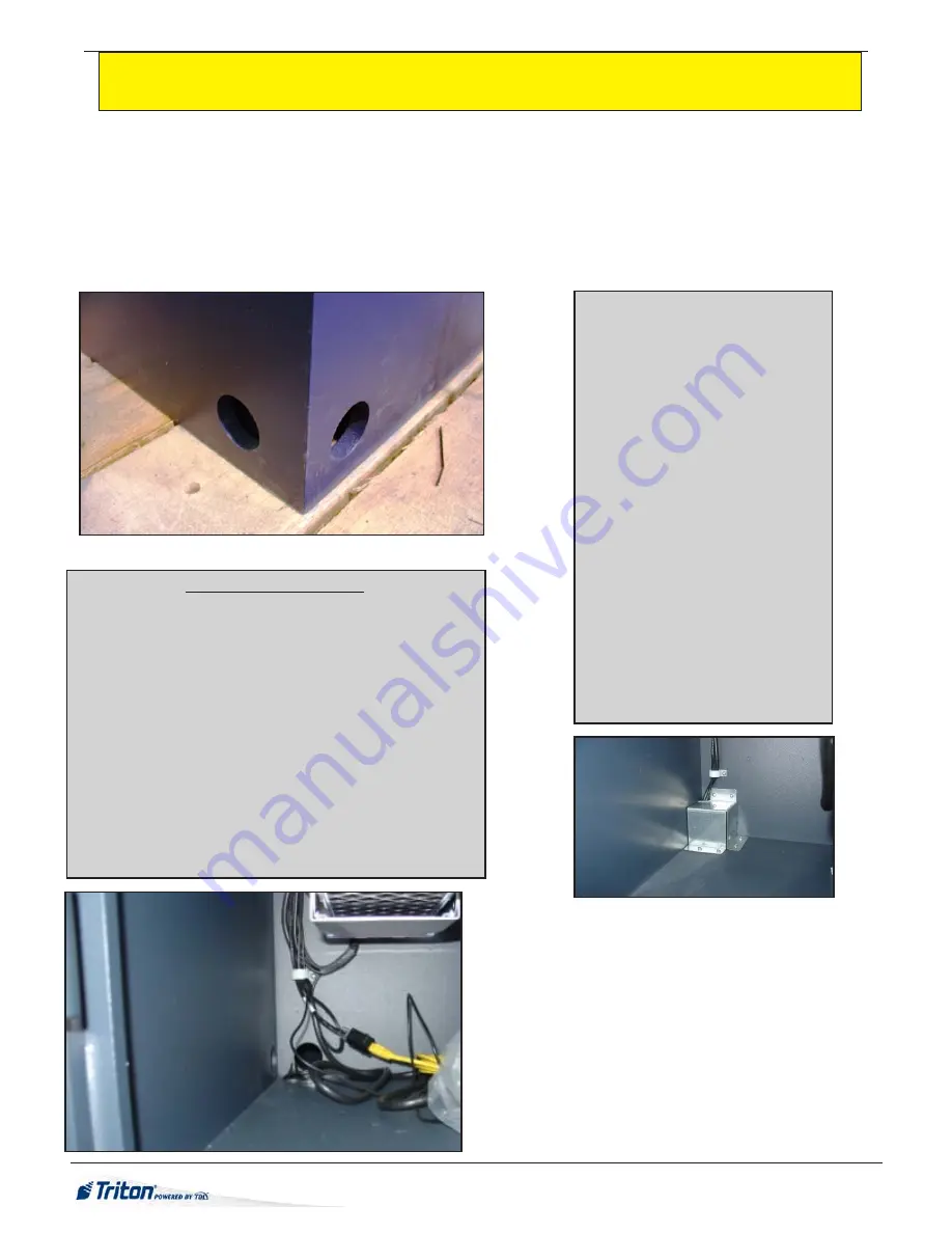
1. Route the AC power cord and the TCP/IP cable through either the main or alternate cable access hole
(as applicable, see figure
1
). (Communications capability is limited to a remote computer using Triton Connect and VersaLink)
2. Connect the AC power cord and communication cable to their respective facility outlets.
NOTE:
Before you start, unlock and open the control panel. Verify that the power switch on the unit’s power supply is in the
off
(0) position. Close the control panel.
3. Secure/plug the unused access hole with the grommet or plug provided.
Power Outlet Accessibility
Whether you are installing a new AC socket outlet or plan to use
an existing outlet to supply power to the VersaSafe™, make sure
the following requirements are met:
1.
The outlet is located near the equipment. Extension cords are
not recommended.
2.
AC power for the terminal should come from a dedicated
source with an isolated ground. The unit is designed to work
on an IT (Isolated-Terra) type power system having a phase-
to-phase voltage not exceeding 240 volts.
3.
The outlet is easily accessible and will not be blocked once
the equipment is installed and anchored.
POWER SUPPLY CORD -
SPECIFICATIONS
For European applications, the power
supply cord must conform to the fol-
lowing specifications:
1. Two-conductor with Physical Earth
(PE) ground.
2. IEC 320 molded connector on one
end and molded plug on the other
end.
3. Certified for country of installation.
4. Rated minimum H05VV-F with
minimum 0.75 mm2 (except where
specific countries require 1.0 mm2)
conductors.
5. Maximum length: 3 meters.
Figure 1
Power cable cover
Figure 2
Corner holes allow passage of power, ground and
communication wiring. Wiring to an external mount-
ed antenna will run through the access holes and
connect to the TDL Gateway wireless communica-
tions systems. The USB cable provides power to the
wireless modem.


