13
V
ersa
s
afe
TM
I
nsTallaTIon
After final connection of power and communication, and ensuring the cabinet is secured to the floor
or optional plinths, install the power cable cover, (see figure 2) with the 6 (six) screws provided.
The cover and screws are in the accessory bag. This must be accomplished to ensure the physical
security provided by the VersaSafe
TM
.
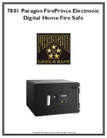
Keep in mind when mount-
ing antenna on outside
of unit that its location
will directly affect signal
strength of the TDL Gate-
way. If a weak signal is
encountered and does not
improve, it may be neces-
sary to obtain a booster
amplifier. The amplifier
installs between the TDL
Gateway and the antenna
and requires AC power.
Contact Triton technical
support for further details.
A USB cable will connect the wireless modem to the
system’s main board and serve as its power supply.
Use TY wraps to bundle cables if necessary.
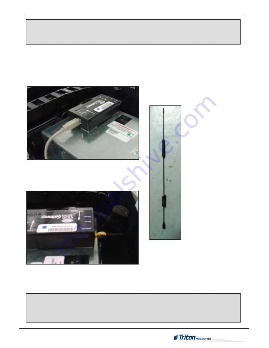
The TDL Gateway modem will mount atop the units power supply. A USB cable will provide power
to the unit from the system’s main board,
(see figure 3).
The antenna will mount atop the VersaSafe
unit with a magnetic holder and the connection cable will run into the cabinet through holes in lower
corner of unit. The cable will connect to the wireless modem with threaded cable,
(see figure 4).
If
weak signal occurs, a booster amplifier may be necessary to aid communications.
Figure 3
The TDL Gateway mounted on top of unit’s power
supply provides wireless communication. Screw on
adaptor connects the modem’s antenna.
Figure 4
Figure 5
NOTE:
New VersaSafe units will come pre-loaded with the current 2.4.4 SP5 software. If upgrad-
ing unit, do not plug in TDL Gateway modem until software version 2.4.4 is loaded to system. If
2.4.4 software is not loaded, an error code will result notifying the user that the device is not found.


