background image

Survey Pro GPS Quick Start Guide 

13 


2.


Select an existing job file point, and check the boxes to set 

if you want to 

Use This GPS Control Point For:

 horizontal, 

vertical, or horizontal and vertical control. 

3.


Level the pole over the point and tap  

Start Control Point Occupy…

 to begin an occupation on the 

selected point and open up the Occupy Control screen. 

4.


When you are satisfied with the GPS observation, tap 

Accept

 to create the GPS control point and go back to the 

Localization Status page. 

5.


If you have enough control, the wizard will advance to the 

Localization Check page.  If you do not yet have enough 
control, repeat steps 1 to 4 until the wizard advances to 

the next page. 

6.


If you wish to proceed directly to data collection without 

collecting the control required to solve the localization, 
you can tap 

Start Now

.  A temporary localization will be 

applied so you can start data collection. 

Note: You must establish the control to solve the localization 
at some point in order to calculate the proper local 

coordinates of your base and any points you measured while 

the temporary localization was in place.  This step can be 
completed in the field, or later in the office if desired. 

Localization Check (Collect Check Point) 

The Localization Check page shows you the base point name 

and the name of the points used for the GPS Backsight or 

GPS Resection.  The display will prompt you to collect an 
additional GPS control point to check the setup. 
7.


When you are ready to start a GPS control point collection 
for your check, tap 

Occupy Check >

 to open the Select 

Check Point screen. 

8.


Select an existing job file point, and check the boxes to set 

if you want to 

Use This GPS Control Point For:

 horizontal, 

vertical, or horizontal and vertical control. 

Summary of Contents for SURVEY PRO

Page 1: ...SURVEY PRO Basic GPS Quick Start Guide ...

Page 2: ...ting a Remote Rover 9 Start Rover Receiver 9 Select Remote Base Point 10 Solving a Localization 11 Localization Status Collect Control Points 12 Localization Check Collect Check Point 13 Localization Results 14 GPS Data Collection 15 Data Collection Screen 16 Traverse Base 17 Data Collection Settings 17 Stake Out 18 Post Processing Data Collection 18 Post Processing Settings 19 Start Receiver Reco...

Page 3: ...te You can use Foresight DXM or Spectra Precision Survey Office to create and transfer geoid and datum grid files Make sure you have all of your GPS equipment The following is a check list for a base rover radio RTK o EPOCH25 base receiver with EPOCH L1 L2 antenna and antenna cable o Serial cable or Bluetooth dongle for the base receiver o External Pac Crest transmitting radio and antenna with ant...

Page 4: ...ach and leave the base receiver in the case using the extended antenna cable 3 Connect the DB9 standard 9 pin serial end of the radio serial cable to serial port 1 on the bottom of the base receiver and secure it with the thumb screws Connect the Lemo round end of the radio serial cable to the serial port on the radio Note If you are using a serial cable for the data collector to talk to the base ...

Page 5: ... 2 Connect the GPS antenna cable to the bottom of the rover receiver 3 Connect the radio antenna to the bottom of the rover receiver unless you are using a cell phone for your modem connection 4 Connect the serial cable or Bluetooth dongle to serial port 2 on the bottom of the rover receiver and secure it with the thumb screws Note If you are using a serial cable for the data collector to talk to ...

Page 6: ...o using the base rover radio modem link If you anticipate interference from another CMR base on your radio channel you can check the Use CMR Station Index box and specify an index for your RTK corrections 4 If you are using a radio you are finished with the RTK hardware settings in Survey Pro If you wish to do post processing data collection simultaneous with RTK go to step 8 to configure your rec...

Page 7: ... projection such as a US State Plane zone If you are starting a new survey on a site you can open a new job and enter a starting coordinate When you start the first GPS survey in a new job with just one point a default coordinate system for ground level distances will automatically be setup for you If you are starting a GPS survey on an existing job site you can open a job file with the coordinate...

Page 8: ...database Choose the appropriate region and zone from the drop down lists 2 Tap the Use Geoid check box if you want to use a geoid with this zone and select a geoid model from the drop down list 3 Tap Finish to set the selected coordinate system When you reopen a job that already has a coordinate system defined whether it is a default projection in Ground TDS Localization mode or a selected zone in...

Page 9: ... the Measured height and select the correct Measure To mark in the drop down box If required you can also enter the base antenna serial number for book keeping Note When the base is on a variable height tripod you usually measure a slant height from the setup point to the top of the notch on the EPOCH L1 L2 antenna If the base antenna is on a fixed height tripod you would enter the fixed height an...

Page 10: ...oint with the base setup You will always see this screen for the first GPS setup in a job without a coordinate system You will also see this screen if you set the base on a new location in a job that already has a coordinate system Select the radio button for either new or known point and enter the Base Point name in the edit field When Survey Pro finds a unique point in the job file that matches ...

Page 11: ... 9 If the coordinate system is ready for data collection tap Finish to complete receiver setup and go to the data collection screen You are now ready to begin surveying 10 If the coordinate system requires a localization tap Next to complete receiver setup and go to the sequence of pages for solving a localization described after the remote rover setup section Note If you have a Recording Interval...

Page 12: ...t to the bottom of the EPOCH 25 receiver Be careful not to confuse this measure to mark with the bottom of the antenna 3 When you have the antenna height and measure to mark set tap Next Select Remote Base Point 4 The user interface shown on the Select Base Point page will depend on the base position received at the rover and whether or not any GPS points or a GPS coordinate system exists yet in t...

Page 13: ...y default and will always start with the characters VRS 5 Review the choice of base point name and tap the button on the bottom right of the screen This button will be labeled either Finish or Next 6 If the coordinate system is ready for data collection tap Finish to complete receiver setup and go to the data collection screen You are now ready to begin surveying 7 If the coordinate system require...

Page 14: ...r creates the second GPS control point When doing a GPS Resection both GPS control points are created by occupying a known point with the rover In Mapping Plane mode since the orientation of the coordinate system grid is known with respect to GPS measurements you only need one control point In mapping plane mode if you setup on a known point no GPS backsight is required When you setup on a new poi...

Page 15: ...d to solve the localization you can tap Start Now A temporary localization will be applied so you can start data collection Note You must establish the control to solve the localization at some point in order to calculate the proper local coordinates of your base and any points you measured while the temporary localization was in place This step can be completed in the field or later in the office...

Page 16: ...ot a temporary one it was solved with the minimum required control and is therefore valid However this solution was not checked and you should gather at least one additional check point for GPS control in order to verify the solution Localization Results The Localization Results page shows the results of the current localization solution for the GPS Backsight or GPS Resection Before this screen is...

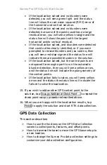
Page 17: ...olved but the control points are not spaced far enough apart to run the automatic blunder detection then you will see a yellow arrow and the status line will indicate the poor geometry of the control points If the localization fails to solve you will see a yellow arrow and the status the status line will indicate the failure to solve the localization 15 If you wish to add another GPS control point...

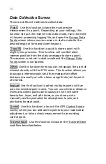
Page 18: ...is not opened Offset Use this function when you can not occupy the point of interest directly with the RTK rover This function allows you to occupy a reference point and then measure an offset distance manually or with a laser range finder to the point of interest Feature Use this function to collect multiple points with an auto incremented point name You can use a time or distance interval to col...

Page 19: ...n For both cases after you have moved the base receiver and are ready to restart the RTK survey the Start Survey wizard will open and guide you through the base setup at the new location Data Collection Settings Use the Job Settings Measure Mode card to control how the receiver collects data and what criteria to check before accepting GPS positions Receiver Dynamics Static on Occupy will set the r...

Page 20: ...Occupying When you first open any GPS staking screen the GPS receiver is in dynamic moving mode This is necessary as you navigate to the design point and is indicated on the screen with the toggle button in the Roving position When you arrive at the design point if you want to take a more precise measurement you can switch the receiver to static mode by tapping the toggle to Occupying This will ch...

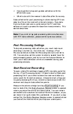
Page 21: ... special layer for post processing points and to turn on the Session Monitor to warn you if data collection criteria is exceeded during post processing sessions Start Receiver Recording To open a data file and begin logging GPS raw data go to the Survey Post Processing screen Choose to start a Static post processing file if you intend to leave the receiver stationary over a point for the entire se...

Page 22: ...g data collection Store Point In Receiver and job file will mark the event in the post processing logging file and store a point in the Survey Pro job You can use this mode to save attribute or layer information in the Survey Pro job file Receiver file only will only mark the event in the post processing logging file In this mode the Site ID does not need to be a unique point name and nothing is s...

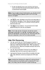
Page 23: ...nceling a point occupation event after it is started Therefore even if you cancel the occupation in Survey Pro you will still likely see the point occupation when the file is post processed Data File Processing You can use the Survey File Management screen in Survey Pro to download post processing data files T01 from your receiver to the hand held Then use Spectra Precision Survey Office to downlo...

Page 24: ...TRIPOD DATA SYSTEMS INC P O Box 947 Corvallis Oregon 97339 0947 Technical Support 541 757 7254 or visit www tdsway com ...

Reviews: