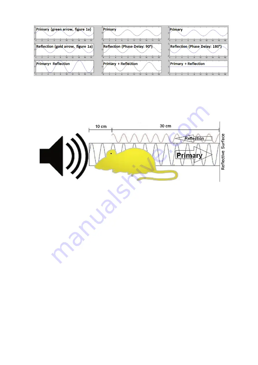
Figure 2 - The summation of signals during constructive interference (left), partial interference (middle), and
fully destructive interference (right). The level of interference is based on the frequency-speci
fi
c phase delay,
which is based on wavelength and distance of travel for the primary and re
fl
ected signals.
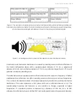
Figure 3 - A standing wave that is present at the subject's ear when the re
fl
ection returns
Constructive and destructive interference is caused by standing waves and their re
fl
ections. In
the model con
fi
guration above, with a speaker-subject distance of 10 cm, a subject-wall
distance of 30 cm, and a re
fl
ective distance of 70 cm, any stimulus longer than 0.175 ms will
generate a temporary standing wave.
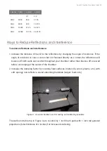
The table below shows speaker position offset tolerances with respect to frequency. It further
emphasizes how re
fl
ections can affect standing waves and tone pips at various frequencies.
The
∆
value is the relative distance or tolerance between fully constructive and fully destructive
interference. This value represents a 180° phase shift over a re
fl
ected distance or
λ
/4. The
speaker-subject spacing and tolerance is very sensitive to change, especially at higher
frequencies. If a speaker's position is displaced by a distance of 2.68 mm, for a 32 kHz
stimulus, the re
fl
ection's phase is shifted 180° and could greatly reduce the perceived intensity.
Sound Chamber Fundamentals | 51

