


3-44
System 3
RX7 Stimulator Base Station
DB25
Connector
Pinouts
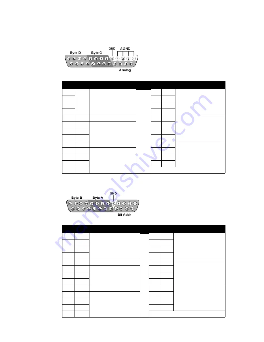
Multi
I/O
Digital
I/O
Pin
Name
Description
Pin Name
Description
1
AGND Analog Ground
14
A1
Analog Output Channels
2
15
A2
3
16
A3
4
17
A4
5
GND
Digital I/O Ground
18
C0
Byte C
Word addressable
digital I/O
Bits 0, 2, 4, and 6
6
C1
Byte C
Word addressable
digital I/O
Bits 1, 3, 5, and 7
19
C2
7
C3
20
C4
8
C5
21
C6
9
C7
22
D0
Byte D
Word addressable
digital I/O
Bits 0, 2, 4, and 6
10
D1
Byte D
Word addressable
digital I/O
Bits 1, 3, 5, and 7
23
D2
11
D3
24
D4
12
D5
25
D6
13
D7
Pin
Name
Description
Pin Name
Description
1
BA0
Bit Addressable digital I/O
Bits 0, 2, 4, and 6
14
BA1
Bit Addressable digital I/O
Bits 1, 3, 5, and 7
2
BA2
15
BA3
3
BA4
16
BA5
4
BA6
17
BA7
5
GND
Digital I/O Ground
18
A0
Byte A
Word addressable digital I/O
Bits 0, 2, 4, and 6
6
A1
Byte A
Word addressable digital I/
O
Bits 1, 3, 5, and 7
19
A2
7
A3
20
A4
8
A5
21
A6
9
A7
22
B0
Byte B
Word addressable digital I/O
Bits 0, 2, 4, and 6
10
B1
Byte B
Word addressable digital I/
O
Bits 1, 3, 5, and 7
23
B2
11
B3
24
B4
12
B5
25
B6
13
B7


