


3-40
System 3
RX7 Stimulator Base Station
Using
the
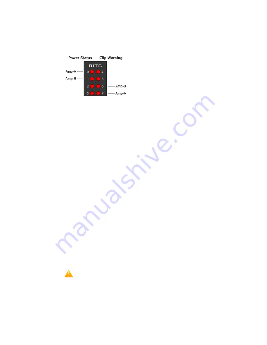
Bits
Lights
to
Display
Amplifier
Status
Note: Because clip warning and amplifier status are always displayed using the Amp
lights (located directly to the right of each fiber optic port), TDT recommends using
the Bits lights for other applications. See “Amp Status and Clip Warning Lights ” on
page 3-39, for more information.
When the Bits lights are configured to display the amplifier status, the left column of
lights indicates the power status and the right column indicates a clip warning for the
corresponding amplifier.
“Amplifier Status Patterns” on page 3-39 shows the light pattern and corresponding
amplifier status for the power status lights (0 - 3). Clip lights flash very rapidly
when any channel on the connected amplifier produces a voltage approaching the
maximum input of the amplifier.
Analog
Output
The RX7 is equipped with four channels of 16-bit PCM D/A. The sampling rate is
user selectable up to a maximum of ~100 kHz. The D/A is DC coupled and has a
built-in upsampler for improved audio playback. The upsampler is controlled through
one of the RX7's programmable bits and can be turned off to allow the D/A to
drive external devices such as a stimulator. Channel one analog output can be
accessed via a front Panel BNC (DAC-1). All four analog channels can be
accessed via the DB25 Multi I/O connector (pins 14 – 17).
Important!
When using the RX7 with the stimulus isolator, the sampling rate set for this device
cannot exceed ~25 kHz—a limitation of the fiber optic connection between the RX7
and the stimulus isolator.
Digital
I/O
The RX7 base station has 40 digital I/O lines. Eight bits are bit-addressable. The
remaining 32 bits are four word-addressable bytes. Digital I/O lines are accessed
via the two 25-pin connectors on the front of the RX7. See the “Digital I/O Circuit
Design” section of the
RPvdsEx Manual
for more information on programming the
digital I/O.
CAUTION!: The first eight bits of bit-addressable digital I/O on RX devices
are unbuffered. When used as inputs, overvoltages on these lines can cause severe
damage to the system. TDT recommends when sending digital signals into the
device, never send a signal with amplitude greater than five volts into any digital
input.


