background image

3-42

System 3

RX7 Stimulator Base Station

Bit


Codes


for


Controlling


the


Bit


Lights


(Boxes


12

14)

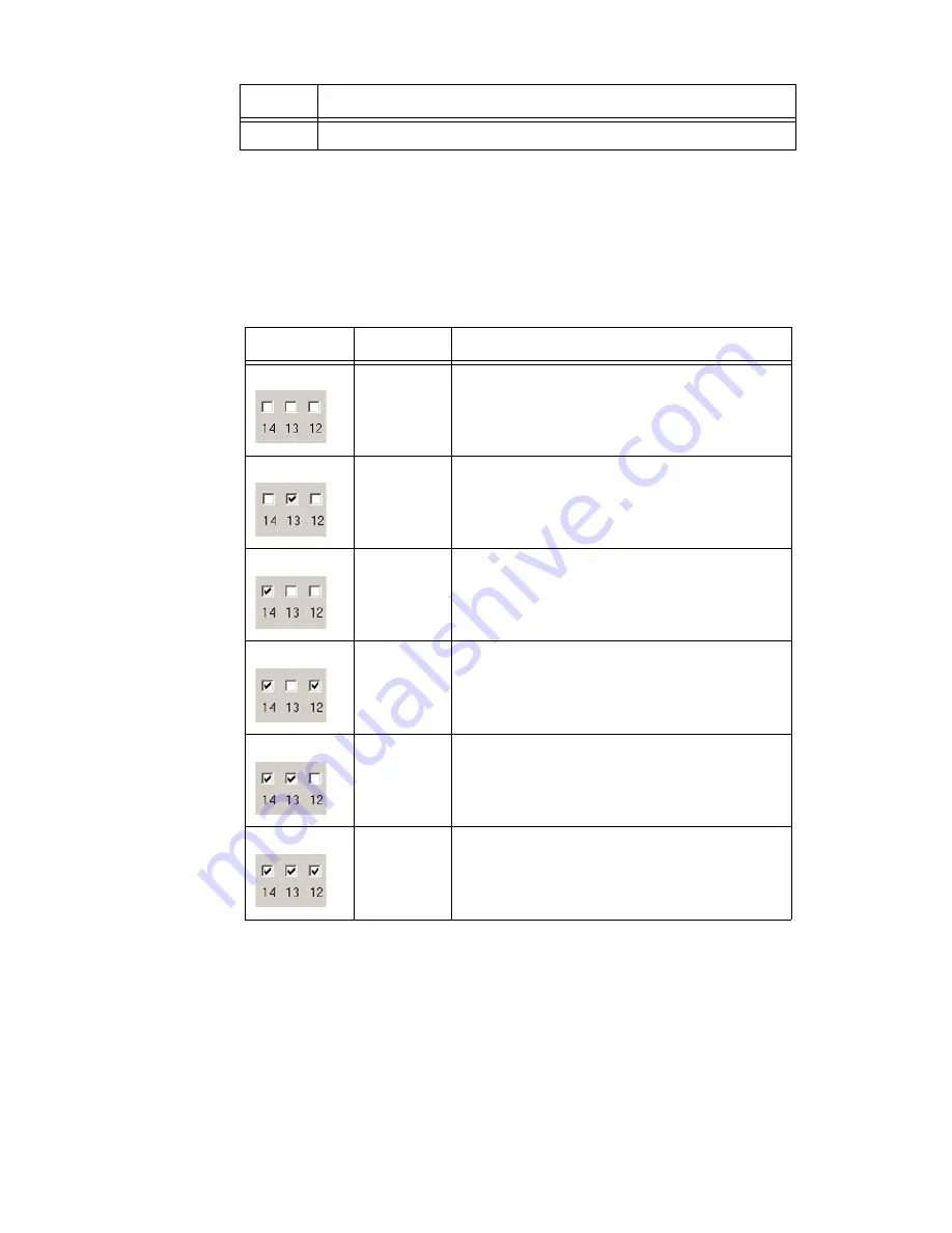
By default, check boxes 12 –14 in the Edit I/O Setup Control dialog box (previous 

diagram) are cleared to create the bit code 000. This configures the eight front 

panel Bits lights to act as activity lights (glow when high) for the eight bit 

addressable digital I/O lines. The Bits lights can also be configured to provide 

information about amplifier status or act as activity lights for any of the other four 

bytes of digital I/O. 

XLink

The XLink is not supported at this time.

RX7


Technical


Specifications

The RX7 is designed for use with the MS16 stimulus isolator. The RX7 is also 

equipped with a fiber optic input port for use with Medusa or Adjustable Gain 

preamplifiers.

15

Setting the bit to one will disable the D/A upsampler.

Bit Flags

Bits set to 1

Bit Lights Used For …

000

None

Logical level lights for bit-addressable I/O lines

010

13

Amplifier Clip Warning/Power Status display

100 

14

Enable logical level lights for byte A

101

12, 14

Enable logical level lights for byte B

110

13, 14

Enable logical level lights for byte C

111

12, 13, 14

Enable logical level lights for byte D

Bit # 

Description

Summary of Contents for RX7

Page 1: ...3 The RX7 includes 40 bits of digital I O analog output and can include one or two fiber optic input ports for acquisition of digitized data from Medusa preamplifiers Acquired signals can be filtered...

Page 2: ...e information from the I O controller and the shared memory The master DSP supervises overall system boot up and operation The master DSP also acts as the main data interface between the zBus host PC...

Page 3: ...delay is taken care of for the user in OpenEx when Timing and Data Saving macros are used See MultiProcessor Circuit Design in the RPvdsEx Manual for these and other multiprocessor circuit design tec...

Page 4: ...Port Stimulator The output port labeled Stimulator can be used to transfer microstimulation waveforms to the MS16 MS4 Stimulus Isolator and or to control its digital output See the MS4 MS16 Stimulus I...

Page 5: ...he connected amplifiers When an amplifier is not connected the Amp light will flash in a slow steady pattern The light is lit when the amplifier is connected and begins to flash quickly when the volta...

Page 6: ...n upsampler for improved audio playback The upsampler is controlled through one of the RX7 s programmable bits and can be turned off to allow the D A to drive external devices such as a stimulator Cha...

Page 7: ...x and select the RX7 Elec Stimulator from the list The dialog expands to display the Device Configuration Register 3 Click Modify to display the Edit I O Setup Control dialog box In this dialog box a...

Page 8: ...four bytes of digital I O XLink The XLink is not supported at this time RX7 Technical Specifications The RX7 is designed for use with the MS16 stimulus isolator The RX7 is also equipped with a fiber o...

Page 9: ...or Five Memory 128 MB SDRAM Shared D A 4 channels 16 bit PCM Sample Rate Up to 97 65625 kHz 8X upsampled to 200 kHz default operation Frequency Response DC Nyquist 1 2 sample rate Voltage Out 10 0 Vo...

Page 10: ...ts 0 2 4 and 6 10 D1 Byte D Word addressable digital I O Bits 1 3 5 and 7 23 D2 11 D3 24 D4 12 D5 25 D6 13 D7 Pin Name Description Pin Name Description 1 BA0 Bit Addressable digital I O Bits 0 2 4 and...

Reviews: