

114-13233
Rev B
10
of 13
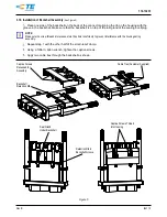
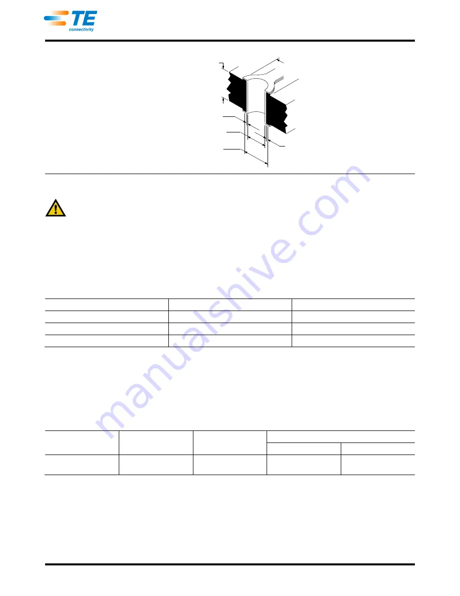
Figure 10
3.15.
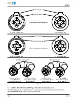
Placement
CAUTION
Connectors should be handled only by the housing to avoid deformation, contamination, or damage to the contacts.
When placing connectors on the pc board, make sure that the contacts are aligned and started into the
matching holes before seating the connector onto the pc board.
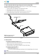
3.16.
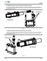
Soldering Connectors
The PC Board Quadrax Connector can be soldered with wave, vapor phase, or infrared reflow processes,
provided the temperatures and exposure time are within the ranges specified in Figure 11. TE recommends the
use of SN60 or SN62 solder for the connectors. Refer to Paragraph 2.4 for instructional material that is
available for establishing soldering guidelines.
SOLDERING PROCESS
TEMPERATURE
TIME (At Max Temperature)
Wave
260°C [500°F] (Wave Temperature)
5 Seconds
Vapor Phase
215
°
C [419
°
F]
5 Minutes
Infrared Reflow
230
°
C [446
°
F]
5 Minutes
Figure 11
A.
Flux Selection
Contact solder tines must be fluxed prior to soldering with a mildly active, rosin base flux. Selection of the
flux will depend on the type of pc board and other components mounted on the board. Additionally, the
flux must be compatible with the wave solder line, manufacturing, health, and safety requirements. Call
the Product Information phone number at the bottom of page 1 for consideration of other types of flux.
Some fluxes that are compatible with these connectors are provided in Figure 12.
FLUX TYPE
ACTIVITY
RESIDUE
COMMERCIAL DESIGNATION
KESTER
ALPHA
Type RMA
(Mildly Activated)
Mild
Noncorrosive
186
611
Figure 12
B.
Cleaning
After soldering, removal of fluxes, residues, and activators is necessary. Consult with the supplier of the
solder and flux for recommended cleaning solvents. The following is a listing of common cleaning solvents
that will not affect the connectors for the time and temperature specified. See Figure 13.
KESTER AND ALPHA are trademarks of their respective companies.
Board Thickness 1.60 [.063] Nominal
Pad Diameter (As
Required)
Tin or Tin/Lead Thickness (As Required)
Dia of Finished Hole After Plating 1.07 [.040] Min●
Drilled Hole Diameter (As Required)
Copper Thickness (As Required) (Maximum
Hardness of Copper to be 150 Knoop)
●Ground Legs 1.65 [.065] Min.


