
114-13233
Rev B
4
of 13
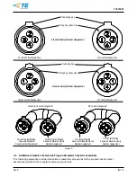
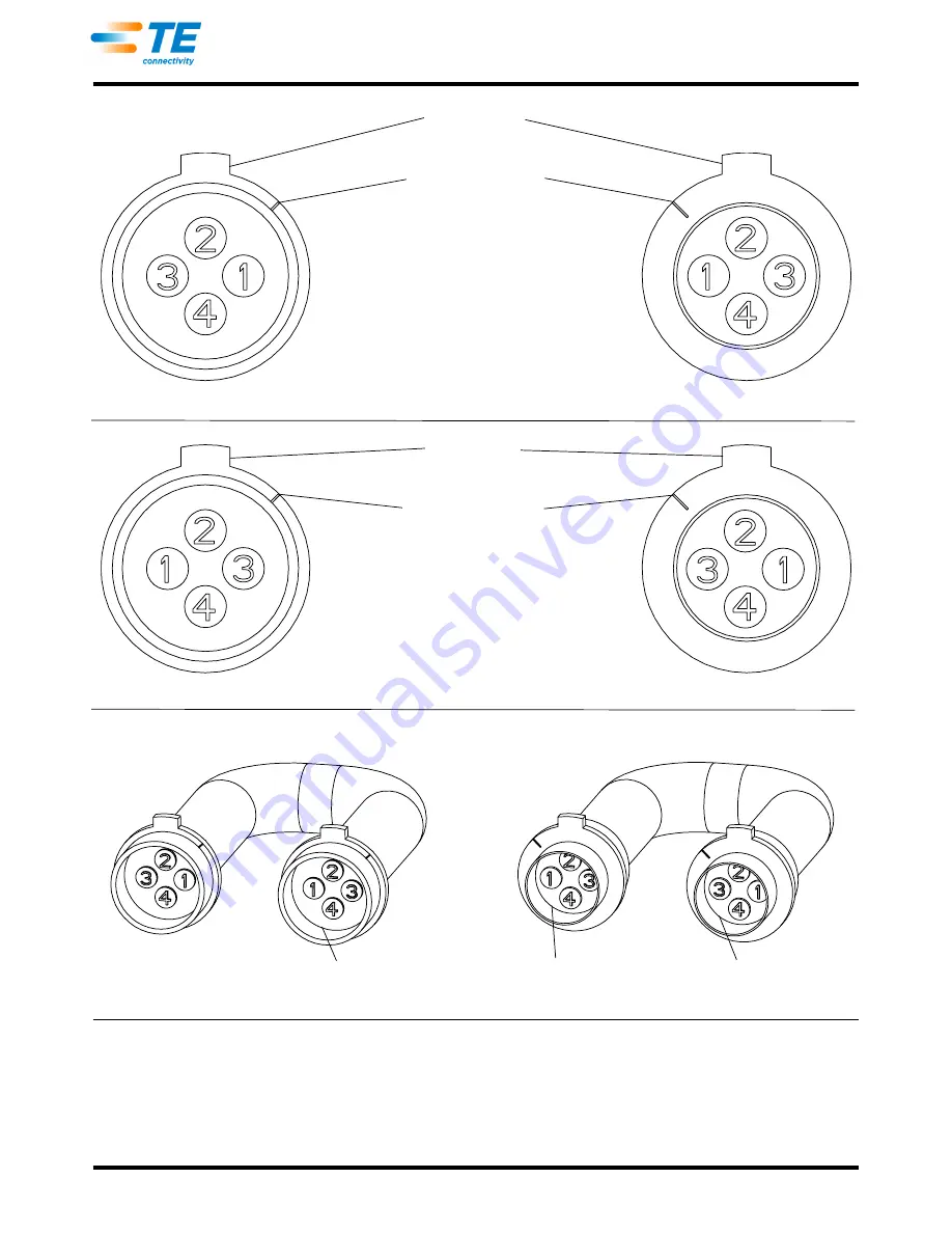
Figure 2
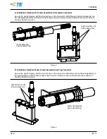
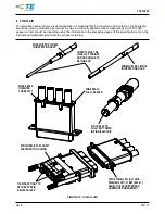
3.9.
Installation of Quadrax Contacts into Plug and Receptacle Connector Assemblies
The following paragraphs provide information on assembly procedures for the pin and socket contact
assemblies installed in the receptacle and plug connectors.
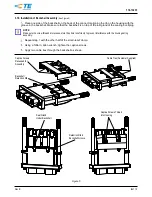
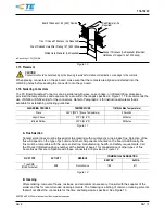
Positioning Key
Wiring Key (Index Line)
Standard Cavity Number Assignment
Socket Contact Mating Face
Pin Contact Mating Face
Socket Contact Mating Face
Pin Contact Mating Face
Positioning Key
Wiring Key (Index Line)
Reverse Cavity Number Assignment
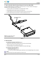
Socket-to-Socket Arrangement
Pin-to-Pin Arrangement
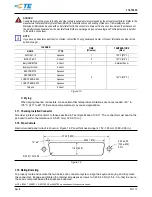
Socket Contact Mating
Face with Reverse Cavity
Number Assignment
Socket Contact Mating
Face with Standard
Cavity Number Assignment
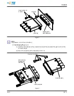
Pin Contact Mating
Face with Reverse Cavity
Number Assignment
Pin Contact Mating
Face with Standard Cavity
Number Assignment