408-78067
Rev A
3
of 4
4.
HEADER CONNECTOR
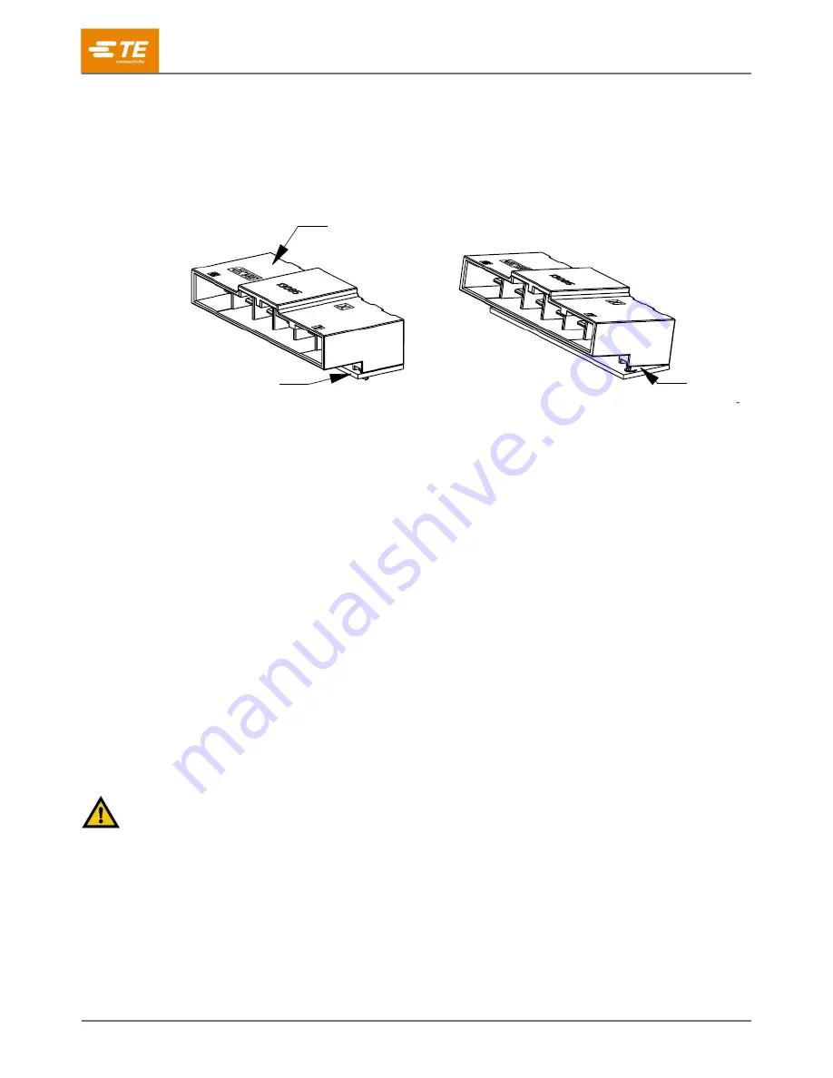
The header connector is PCB installable connector with metal contact assembled. Horizontal type
shown in Fig.4 is available. Recommended PCB thickness is 1.6mm~2.4mm±0.1. Before soldering
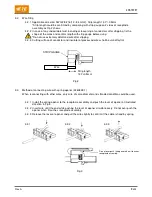
procedure, push the header connector straightly until the retention legs are fixed to the holes on PCB
and confirm no gap between connector and PCB.
Fig. 4
4.1.
Recommended PCB dimensions
Through-hole type PCB is recommended for soldering of D5900 header connector. Recommended PCB
dimensions are defined on the customer drawing.
4.2.
Flow solder mounting
This product is lead-free compatible product. An appropriate temperature profile is mandatory for the
soldering procedure. Please refer to Product Specification 118-140022 for details.
4.3.
Soldering procedure by hand
Please refer to Product Specification 118-140022 for details.
5.
MATING
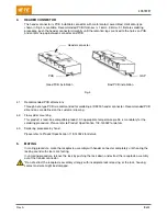
In mating procedure, mate the receptacle assembly with header connector completely until hearing the
locking sound with clear click feeling.
In unmating procedure, release the lock by pushing the lock down and extract the receptacle assembly
out of the header connector.
*Do not extract the receptacle assembly strongly with incomplete lock releasing, or the lock, housing,
contact and wire might be damaged.
Header connector
PCB
Good PCB installation
Bad PCB installation
GAP


