409-35011
Rev C
43
of 54
NOTE
Cutting wheel can only be installed in one orientation. If cutting arm cap will not fit, check orientation of cutting wheel (see
Figure 45).
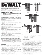
(7) Carefully install the Cutting Arm Cap onto the Cutting Arm.
(8) Insert the (2) socket head cap screws and tighten securely.
(9) Repeat for all 3 wheels.
Remove tooling change tool.
Figure 45
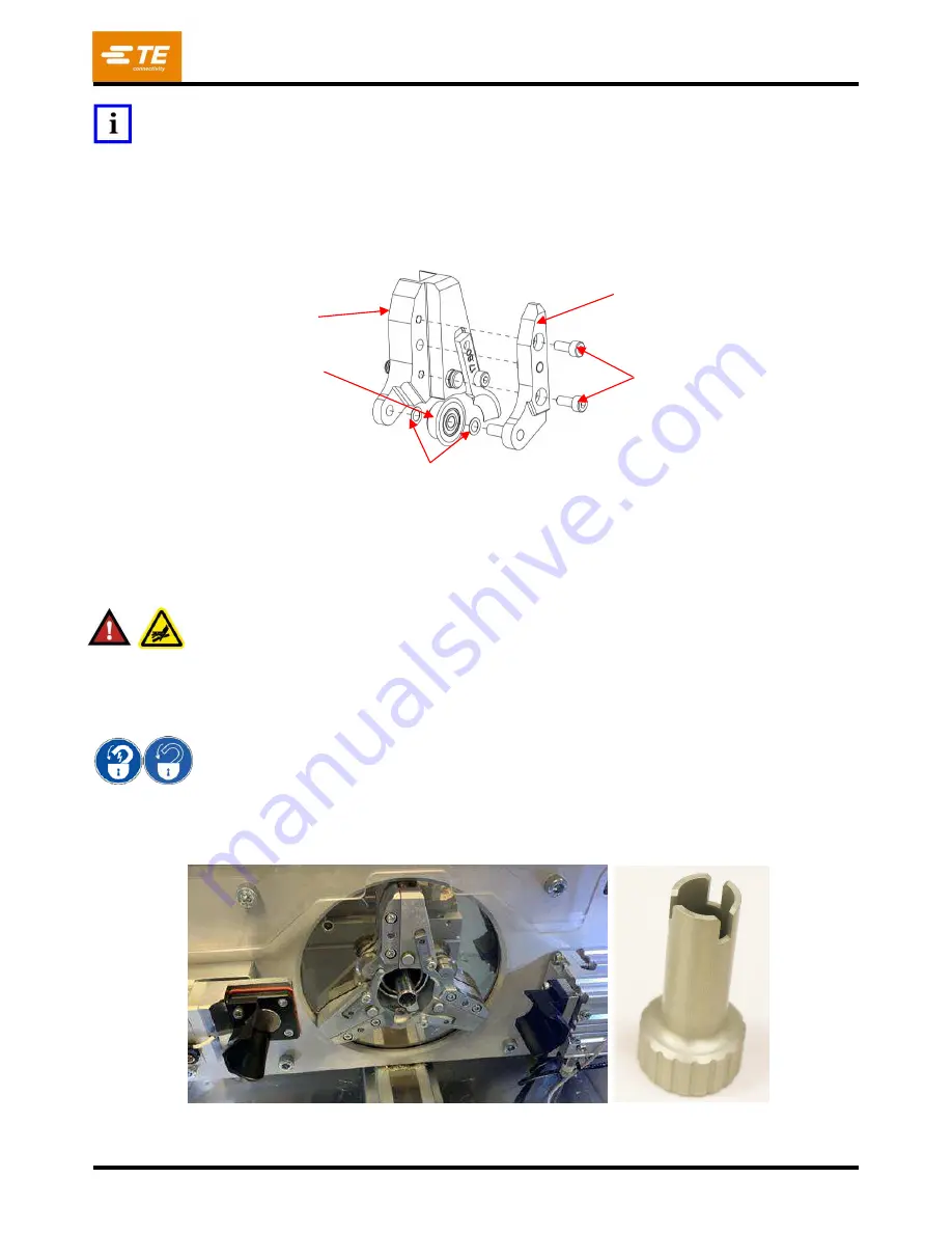
8. Mandrel (see Figure 46)
a. To change the Mandrel:
(1) Bring the mandrel forward by pressing the tooling change button on the production screen.
The machine will retract the wire clamp and cable sensor, and move the mandrel to its most
forward (outward) position.
DANGER
The Mandrel tip and Contour Blades represent dangerous cut and puncture hazards
–
use EXTREME caution when
working in their vicinity.
(2) Power the machine OFF.
(3) Perform LOTO of the machine.
LOTO procedure must be used to perform tooling changeover.
(4) Place the Mandrel Changeover Tool, 2359204-1, onto the mandrel. Engagement will be felt as
the wings of the changeover tool go into the slots in the machine. Tighten to 4 Nm.
(5) Turn the tool counterclockwise to loosen the mandrel and carefully remove it.
Figure 46
Cutting Arm
M4 Socket Head
Cap Screws
Cutting Wheel
Assembly
Shim Rings
Cutting Arm Cap