background image

409-35011


Rev C 

26 

of 54 


Processing 


Typically, day to day processing consists of some of or all the following operations: 

1.  Creating or recalling a Cable 

2.  Creating or recalling an Article 

3.  Revising a Cable 

4.  Revising an Article 

5. 

Standard Operation or “Production”


6.  Importing/downloading Article or Cable via USB flash-drives 


Selecting a cable 

Drop down with names of existing cables on the machine. You can create a new cable or copy from 
an existing cable. You can edit a cable, but only if it is not used in an Article.


Creating a cable 

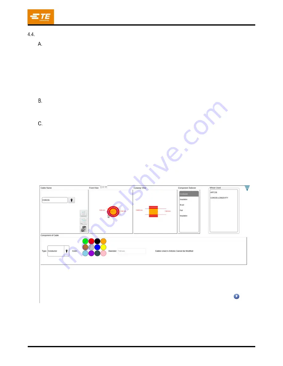
1.  Enter the cable builder screen (see Figure 29) and perform the following steps: 

a.  Choose the Type of layer in the drop down starting from the center of the cable (conductor). 

b.  Choose the color for the layer you want for the cable to show. 

c.  Input dimension from manufacturer cable specifications for the diameter. Dimensions that are 

impossible for the selected layer or may damage the machine will show an error when entered. A 
value that has an error must be amended before the machine will run an article with that cable. 

d.  Press p

lus symbol “+” 

to add the layer.  

e.  Select the pencil button to confirm the entry. 


Figure 29 

2.  As the layers of the cable are added, the Front View, Cutaway View, and Component Selectors will 

show each new layer of the cable. The Front View and Cutaway View show the layers and their 
dimensions, and the component selector shows the type of layer from the center of the cable at the 
top and the outermost layer at the bottom of the list. 

Summary of Contents for HV-CP

Page 1: ...RST 2 1 INTRODUCTION 4 2 SAFETY 4 Standards 5 Ear and Eye Protection 5 Safety Covers Guards 5 Power Connections 6 Safety Interlocks 9 Emergency Stop E STOP Switch 11 3 DESCRIPTION 12 Machine Overview...

Page 2: ...ce and secure to equipment Do not operate the equipment without guards in place Always disconnect air supply and then exhaust system air pressure before performing maintenance or repair on the equipme...

Page 3: ...calling the Tooling Assistance Center regarding service to equipment it is suggested that a person familiar with the device be present with a copy of the manual and drawings to receive instructions M...

Page 4: ...ectric foil from round multi layer cables in preparation for the application of crimped terminals The machine can process cables with conductor cross sectional areas ranging from 10mm2 to 120mm2 8 8mm...

Page 5: ...d procedures during sound testing are in accordance with EN 1218 4 2004 A2 2009 Sound pressure level at the operator position have been measured in accordance with EN ISO 11202 2010 The sound power le...

Page 6: ...for maintenance or repair by inserting a padlock not included into the locking locations see Figure 4 DANGER Never enter the electrical enclosure immediately after turning OFF the machine power switch...

Page 7: ...itch The main air valve will exhaust all residual air from the machine when turned from the Supply SUP position to the Exhaust EXH position The valve may be locked in the EXH position Lock Out Tag Out...

Page 8: ...cycle The airlock valve is designed to improve the performance of the machine by maintaining the grip pressure at all times see Figure 6 It also allows the cable grip to be released if the guard door...

Page 9: ...Off function where the drives are still energized but their motor outputs are disabled and the machine air supply will be turned OFF and residual air pressure will be exhausted Together this effectiv...

Page 10: ...he disabling of the servos or the dropping of air pressure but disables air to the vacuum system CAUTION it is not advisable to open and or empty the scrap bin while a cable prep cycle is in process N...

Page 11: ...ction where the drives are still powered up but their motor outputs are disabled and the air pressure will be dumped which together effectively stops all machine motion The E STOP switch is monitored...

Page 12: ...een assists the operator with setting the processing parameters in first creating an Article i e building a cable profile then setting the run parameters and initiating a production run A different sc...

Page 13: ...quirements Min Machine Working Pressure Min Air Volume Max Preferred Machine Working Pressure Max Supply Line Pressure 0 62 MPa 90 psi 570 Litres min 20 cfm 0 69 MPa 100 psi 0 83 MPa 120 psi Ambient T...

Page 14: ...tightening the knobs Sliding Door The sliding door Top Guard see Figure 13 is the main guarding from the mechanisms of the machine The door has a catch at the top of its range allowing for the door to...

Page 15: ...The gripper will move inward and outward from the machine during the cycle which will cause longer cables to move This will also move the Cable Tunnel that extends outside of the machine guarding Fig...

Page 16: ...se arms rotate to place the blades and wheels for the cutting depth designated in the program 2 Contour Blades Three Contour Blades are used for cutting the insulation and foil layers of the cable Eac...

Page 17: ...raid and inner core to the appropriate depth The Cutting Arm will move the Cutting Wheels into place against the braid and make a complete cut as the head rotates around the mandrel The mandrel is a w...

Page 18: ...the cable end fully see Figure 18 Figure 18 Scrap Bin The machine has an integral vacuum that draws the process refuse insulation foil braid into a removeable scrap bin see Figure 19 During routine p...

Page 19: ...logic controllers safety relays etc for controlling the machine DANGER There are no user serviceable parts in the electrical enclosure This door should not be opened by users call field service for a...

Page 20: ...the OFF position for safety and security proposes Pneumatic Supply Assembly Provides oil free and water free air for machine operation This assembly contains a pneumatic lock out value and a digital...

Page 21: ...mits data over the ethernet using Message Queuing Telemetry Transport MQTT a publish subscribe based messaging protocol By implementing an MQTT message reader a customer can have everything needed to...

Page 22: ...2 2364113 2 4 25 12 2 0 6 8 8 0 6 7 2 2360456 3 2364113 3 2 35 14 4 0 6 10 5 0 7 8 5 2360456 4 2364113 4 1 50 15 8 0 6 12 1 0 7 12 09 12 20 10 5 2360456 5 2364113 5 0 60 16 9 0 6 13 0 1 2 12 99 13 30...

Page 23: ...out of the way The cable will be moved automatically into the blade area and the machine will execute the pre programmed process steps 4 After the cycle is complete the gripper will move the cable tow...

Page 24: ...ed on the left side of the machine see Figure 20 Turning the switch to the OFF position disconnects the incoming power It can be locked out for safety and security proposes Turn it to the ON position...

Page 25: ...row see Figure 27 and select the control panel icon Then select the Login Logout icon from the control panel Figure 27 2 User access based on the administrator admin and other users model The administ...

Page 26: ...the drop down starting from the center of the cable conductor b Choose the color for the layer you want for the cable to show c Input dimension from manufacturer cable specifications for the diameter...

Page 27: ...cable 1 Choose either a default cable or article that is loaded on the machine or a cable or article that had been previously created 2 Choose the layer you want to edit by highlighting it in the Com...

Page 28: ...409 35011 Rev C 28 of 54 4 Plug USB flash drive into one of the machines USB ports located in the Utility Alcove see Figure 31 Figure 31...

Page 29: ...name of your Article backup NOTE After your new article name should be the file extension json this is something that must be entered manually see Figure 32 6 Select Save NOTE A pop up window will app...

Page 30: ...e from a USB flash drive select Import Article from the Article Database Tab under Maintenance see Figure 33 NOTE Make sure your USB flash drive is plugged into one of the USB ports in the Utility Alc...

Page 31: ...v C 31 of 54 8 Choose the Article you wish to upload from your USB flash drive in the window see Figure 34 9 Select Load NOTE A pop up window will appear informing the user that the upload was a succe...

Page 32: ...e or Copy from an Existing Article see Figure 35 Select the process type from the drop down Select the cable from the drop down It is recommended to copy from an existing article if there are paramete...

Page 33: ...h are shown with each line in the article process view and are measure from the tip of the cable The step of the process can be selected and the dimension entered on the right side of the screen If th...

Page 34: ...been attempted there is an advanced parameters option The parameters that can be edited for each step in the process will show as that step is highlighted in the list on the left of the screen For va...

Page 35: ...um system Users can utilize an option to minimize this condition called Bites Bites cut the segment up into segments equal to the strip length for that operation The number of bites chosen will be div...

Page 36: ...re to be used by the HV CP administrator 1 Language Icon To pick a language touch the language icon then select the appropriate language and save it Touch the icon to select the Language screen Choose...

Page 37: ...NOTE Permissions are a method to allow or not allow individual users access to certain tasks or actions that can be performed on the HV CP With the user selected from the drop down list choose the app...

Page 38: ...king screen is used to allow the HV CP to be configured on your LAN Features of the HV CP that require this functionality are the Manufacturing Execution System MES network time server and remote trou...

Page 39: ...crap bin or emptying and ALWAYS wear the proper PPE when removing any loose debris Contour Blades Inspect Contour Blades for nicks gouges burrs etc blades will need to be changed between different cab...

Page 40: ...e of the pulleys it is possible that the mechanism will move Use caution with hand placement when changing tooling LOTO procedure must be used to perform tooling changeover 1 Changeover tooling is in...

Page 41: ...ch the Home button on the production screen see Figure 42 4 Touch the Tooling Change button Figure 42 5 Insert tooling change tool 2361560 1 in the hole see figure 43 Figure 43 Home Button Tooling Cha...

Page 42: ...in and tighten the screw securely 7 Repeat for all 3 blades 8 If only changing contour blades remove tooling change tool Figure 44 7 Cutting Wheels see Figure 45 a To change the Cutting Wheels 1 Bring...

Page 43: ...ill retract the wire clamp and cable sensor and move the mandrel to its most forward outward position DANGER The Mandrel tip and Contour Blades represent dangerous cut and puncture hazards use EXTREME...

Page 44: ...procedures should be done on the intervals given below DANGER Always turn off and lock out the Main Disconnect and the Pneumatic shutoff when performing maintenance on the HV CP machine By Schedule I...

Page 45: ...t parts through your TE Connectivity Representative or call 1 800 526 5142 or send a facsimile of your purchase order to 1 717 986 7605 or write to CUSTOMER SERVICE 038 035 TE CONNECTIVITY CORPORATION...

Page 46: ...functioning 2 Once the machine is received at the facility of use verify that as received the shipment looks like the image in Figure 49 tooling blades mandrels etc may be shipped separately and if so...

Page 47: ...tom of machine Keep forks spread as wide as possible for better stability a Remove Foam Hat PN 2358910 or bubble wrap protecting monitor and corrugated inserts securing Scrap Bin see Figure 50 Figure...

Page 48: ...409 35011 Rev C 48 of 54 2 Remove tie wraps holding the Top Guard in place see Figure 52 Figure 52 3 Remove plate securing a pin to one of the Cutting Arms see Figure 53 Figure 53...

Page 49: ...ng Wire Pull Actuator in place see Figure 54 Figure 54 5 Remove the tie wrap holding the electrical enclosure key in place place in a safe location and the tie wrap holding the main air disconnect val...

Page 50: ...Rev C 50 of 54 6 Remove tie wrap holding Gripper jaws together see Figure 56 Figure 56 7 Remove tie wraps holding the left and right Cable Gate Cylinder in fixed positions see Figure 57 and Figure 58...

Page 51: ...our supplied Foot Levelers to level the machine 2 Pneumatic Supply a The pneumatic supply must be connected to the port provided in the utility alcove in the left side panel of the machine Supply pres...

Page 52: ...ted for at least 10 000 IAC b Install a customer supplied 3 conductor power cord having an appropriate rating for the supply voltage and current capacity at the Main Disconnect c Figure 60 depicts the...

Page 53: ...Disconnect Switch terminals as shown in Figure 62 Figure 62 4 After installing the power cord tighten the cord cable gland to secure the cord Reassemble the Disconnect enclosure by reversing the steps...

Page 54: ...with the regulations in force in the country where the machine is used the user must make sure that waste produced during operation is correctly disposed Disposal of lubricants and parts removed must...

Reviews: