background image

408-35328 

Rev

 A


of 7


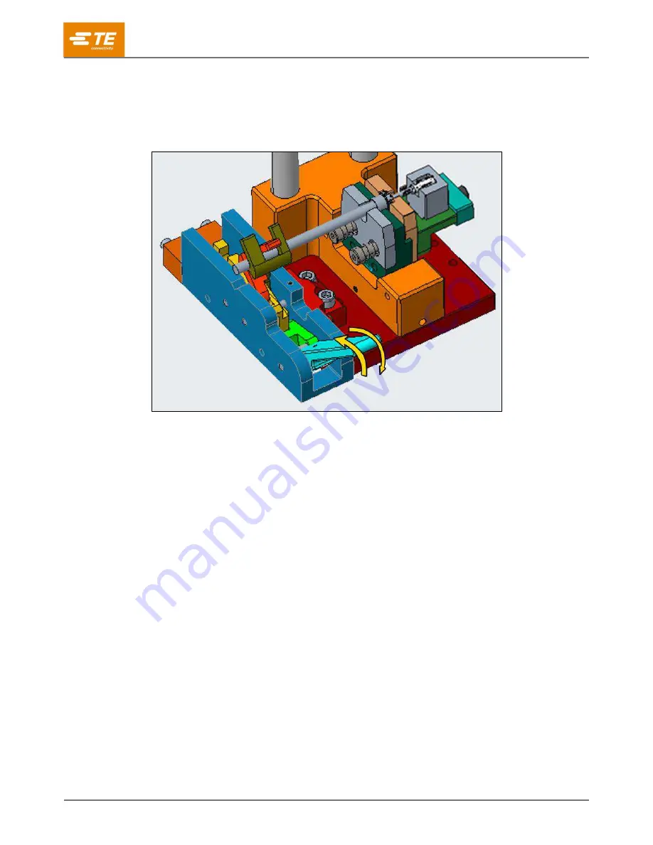
5.  Close the wire clamp to hold the wire in place. 

6.  Cycle the terminator to complete the crimp. 

7.  Open the wire clamp to remove the crimped assembly from the tooling. 

Figure 6: Closing and opening the wire clamp 


5  Inspecting the crimp 

For crimp inspection information, refer to the 114 series application specification listed in Table 1 for the ferrule 
being crimped. 

6  Maintenance and inspection 

Each die assembly is inspected before shipment. When it arrives at your facility, inspect it immediately to 
ensure that it was not damaged during shipping. 

6.1  Daily maintenance 

Make each operator aware of (and responsible for) the following daily maintenance requirements: 


Remove dust, moisture, and other contaminants with a clean, soft brush or soft, lint-free cloth. 

Do not


use objects that could damage the dies or tool. 


When the dies are not in use, store them in a clean, dry area. 

6.2  Periodic inspection 

Regular inspections should be performed by quality control personnel. A record of scheduled inspections 
should remain with the dies or be supplied to personnel responsible for the dies. Perform at least one 
inspection per month. Base your inspection frequency on the amount of use, ambient working conditions, 
operator training and skill, and established company standards. Perform the inspection as follows: 

1.  Remove all contaminants with a clean, soft brush or soft, lint-free cloth. Do not use objects that could 

damage the dies. 

2.  Inspect the crimp area for flattened, chipped, cracked, worn, or broken areas. 

3. 

If damage or abnormal wear is evident, replace the tool or dies. Refer to section 

Error! Reference s

ource not found.

, Error! Reference source not found..


Summary of Contents for HVA HD400

Page 1: ...s 1 Introduction The crimping die assembly Figure 1 is designed to be installed into the modular tool holders listed in Table 1 The crimping die assembly is designed to crimp HVA HD400 ferrules Table 1 Crimping specifications Crimping die assembly Wire size mm Ferrule part number Application specification Modular tool holders 2374311 1 2 5 2371242 1 2371243 1 114 160093 2305470 1 4 2371242 2 23712...

Page 2: ... locator and a ferrule locator assembly Figure 2 NOTE The rear locator and the ferrule locator assembly maintain the ferrule position during the crimping process They are supplied pre assembled to the crimping die Figure 2 Components 1 Shank 4 Nest 2 Crimper 5 Terminal stopper 3 Ferrule locator 6 Ferrule locator assembly ...

Page 3: ...heets Modular tool holder Instruction sheet 2305470 1 408 35048 2326378 1 408 35049 Disconnect electrical power before performing maintenance or repair on this equipment Disconnect air supply before performing maintenance or repair on this equipment To achieve proper orientation of the dies during installation ensure that the alignment dots are facing in the direction of the wire clamp on the modu...

Page 4: ...or die assembly by starting at setting A on the crimp disc and incrementally adjusting to the specified crimp height If the machine has crimp height shut height adjustment refer to the applicable 412 series customer manual for guidance 1 Assemble the ferrule to the prepared wire assembly according to the 114 series application specification listed in Table 1 2 Open the wire clamp by pressing down ...

Page 5: ...rrule locator The crimped contact is inserted in the terminal block stopper The latch on the contact body is in the pocket of the terminal stopper NOTE The crimped contact must fit within the identified surfaces to ensure proper spacing and orientation see Figure 4 Figure 5 Positioning the ferrule ...

Page 6: ...th a clean soft brush or soft lint free cloth Do not use objects that could damage the dies or tool When the dies are not in use store them in a clean dry area 6 2 Periodic inspection Regular inspections should be performed by quality control personnel A record of scheduled inspections should remain with the dies or be supplied to personnel responsible for the dies Perform at least one inspection ...

Page 7: ...er parts by any of the following methods Go to TE com and click the Shop TE Store link at the top of the page Call 1 800 522 6752 Write to CUSTOMER SERVICE 038 035 TE CONNECTIVITY CORPORATION PO BOX 3608 HARRISBURG PA 17105 3608 For customer repair services call 1 800 522 6752 8 Revision summary Since the last revision of this document the following changes were made Initial release ...

Reviews: