background image


114-94052


REV. H1 


17

 of


31


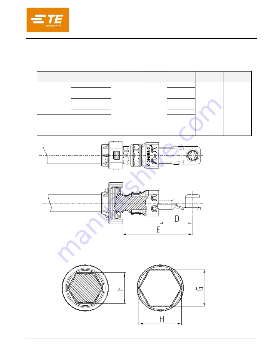
    The following Inspection dimensions at minimum must be verified: 

          Die nachfolgenden Pruefmasse muessen mindestens ueberprueft werden: 
 

Table 8: Inspection dimensions cable assembly 

Tabelle 8: Pruefmasse Leit 


Figure 11: Inspection dimensions of shield crimp  

Abbildung 11: Pruefmasse des Schirmcrimps 

Wire type 

Leitungstyp 

Cross section 

Querschnitt


D ± 1,5  

[mm] 

E  

[mm]  

F ± 0,2 

[mm] 

G ± 0,2  

[mm] 

H  

[mm] 

Coroplast 


16 

28 

max. 59 

-- 

16,6 

max. 21 

25 

12,2 

35 

14,3 

50 

15,5 

Leoni 

25 

12,2 

35 

14,3 

Cablena 

25 

12.2 

KROMBERG 

SCHUBERT 

35 

14.3 

Cross section: Shield crimp 

Querschnitt: Schirmcrimp 

Cross section: Insulation crimp 

Querschnitt: Isolationscrimp 

Summary of Contents for HVP800 2PHI 90

Page 1: ...ange Trademark TE Connectivity TE connectivity logo and TE logo are trademarks Other logos product and or company names may be trademarks of their respective owners Application Specification 114 94052...

Page 2: ...ON OF DELIVERY AND PACKAGING 9 ANLIEFERZUSTAND UND VERPACKUNG 9 3 1 COMPONENTS Komponenten 9 3 2 PACKAGING AND STORAGE Verpackung und Lagerung 10 4 APPLICATION TOOLS VERARBEITUNGSWERKZEUGE 11 3 1 HV 8...

Page 3: ...Figure 3 Before processing slide components onto cabel sheath 13 Figure 4 Cutting cable to length 14 Figure 5 Comb out screening braid 15 Figure 6 Contact crimp 15 Figure 7 Prepare shielding parts fo...

Page 4: ...crimpes 15 Abbildung 10 Pruefmasse des Schirmcrimps 16 Abbildung 11 Montage der Einzeladerdichtung mit der Schutzkappe 17 Abbildung 12 Orientierung Leitungssatz zum Gehaeuse 17 Abbildung 13 Leitungsas...

Page 5: ...erm Wolfgang Balles 07OCT2013 D Comb Out Screening Not Necessary For Cable Shown In Appen Dix See Page 15 Auskaemmen Des Schirmgeflechts Kann Fuer Die Im Anhang Gezeig Ten Leitungstypen Entfallen Sieh...

Page 6: ...u 50mm gemaess LV216 2 eingesetzt werden Der HVP800 90 Stecker ist fuer vier Kodierungen bzw Polarisierungen verfuegbar und mit Hebelausfuehrung fuer geringe Steck und Ziehkraefte Das Stecksystem bein...

Page 7: ...beitungsspezifikation sind die jeweils letztgueltigen Kundenzeichnungen 2 1 1 CUSTOMER DRAWINGS Kundenzeichnungen Table 1 Customer drawings Tabelle 1 Kundenzeichnungen 2POS RECEPTACLE HOUSING 2pol Buc...

Page 8: ...lder with fine adjust Figure Bild 1 HV Praege halter mit Feineinstellung 528040 2 Table frame for hand tool 1 Tischgestell fuer Hydraulische Handzange 9 1579009 1 Hydraulic hand tool 1 Hydraulische Ha...

Page 9: ...Typ B Table A2 Conductor Copper Type B Tabelle A2 Leiter Kupfer feindraehtig flexibel Typ B 3 CONDITION OF DELIVERY AND PACKAGING Anlieferzustand Und Verpackung 3 1 COMPONENTS Komponenten Table 4 show...

Page 10: ...iefziehbuchse 90 Assy 2x 3x 2141212 Deep drawn socket Pin 90 Assy Tiefziehbuchse Pin 90 Assy 2x 3x depend on the cables cross section Abhaengig Vom Kabelquerschnitt 3 2 PACKAGING AND STORAGE Verpackun...

Page 11: ...n 114 94083 Siehe letztgueltige TE Verarbeitungspezifikation 114 94083 4 2 SHIELDING Schirmung The following table contains the required order numbers for application devices and tools Die nachfolgend...

Page 12: ...ions have been validated by TE Alternative cables may be used after en suring performance through validation testing Der nachfolgend beschriebene Prozess zeigt die wesentlichen Schritte der Leitungsve...

Page 13: ...in figure slide protection cover single wire seal shield crimp ferrule 90 and shielding sleeve 90 onto cable sheath so that they are not in crimp work area Schutzkappe Einzeladerdichtung Crimphuelse 9...

Page 14: ...G DIMENSIONS Tabelle 7 Abisoliermasse Figure 5 Comb out screening braid Abbildung 5 Schirmgeflecht auskaemmen ID Cable Design Leitungsaufbau A mm B mm C mm 1 Outer sheath Aussenmantel 32 1 2 Screening...

Page 15: ...screening braid until it stops against the contact as shown in figure 7 Schirmhuelse 90 ueber das Schirmgefecht bis zum Kontaktanschlag schieben wie in Bild 7 dargestellt Figure 7 Prepare shielding pa...

Page 16: ...p shielding sleeve oriented to contact Schirmhuelse 90 orientiert zum Kontakt crimpen It is essential that there are no mistakes in this step because there will be no chance to re work the parts Nach...

Page 17: ...masse Leit Figure 11 Inspection dimensions of shield crimp Abbildung 11 Pruefmasse des Schirmcrimps Wire type Leitungstyp Cross section Querschnitt D 1 5 mm E mm F 0 2 mm G 0 2 mm H mm Coroplast 16 28...

Page 18: ...Abbildung 12 dargestellt Figure 12 MOUNTING SINGLE WIRE SEAL ON COVER SEAL Abbildung 12 Montage der Einzeladerdichtung mit der Schutzkappe Note the alignment of receptacle housing subassembly and cab...

Page 19: ...nzeladerdichtung und Schutzkappe Slide single wire seal and protection cover onto receptacle housing until it is fully locked by audible latch ing The following items at minimum must be inspected and...

Page 20: ...Rippe an dem Isolationseinsatz nur bei Vorserienteil Zum besseren Verstaendnis ist der Isolationstraeger im explodierten Zustand dargestellt Figure 17 Finger protection cap aligned to insulation part...

Page 21: ...rified Die nachfolgenden Pruefungen muessen mindestens durchgefuehrt werden Figure 19 Visual Examination of assembled receptacle housing Abbildung 19 Sichtpruefung des assemblierten Buchsengehaeuses C...

Page 22: ...re ensured by applicator The test parameter should be not exceeding the values shown in point 3 3 TE 108 94268 Die Elektrischen Kennwerte der Produkt Spezifikation 3 3 TE 108 94268 sind von Verarbeite...

Page 23: ...niederdruecken der Verrastungslasche des CPA Adapters Figure 21 Release and actuate lever Abbildung 21 Hebelfreigabe und Betaetigung Rotate lever into plug position until audible click Hebel in Steck...

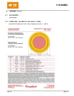
Page 24: ...114 94052 REV H1 24 of 31 8 APPENDIX Anhang 8 1 DATA SHEETS Datenblaetter 8 1 1 COROPLAST No 9 2611 for wire range 16 50mm Datenblatt Coroplast Nr 9 2611 fuer Leitungsquerschnitt 16 50mm...

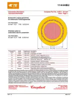
Page 25: ...114 94052 REV H1 25 of 31...

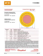
Page 26: ...114 94052 REV H1 26 of 31...

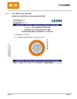
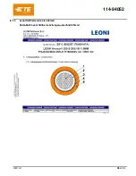
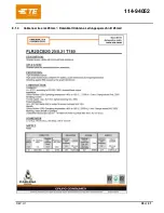
Page 27: ...114 94052 REV H1 27 of 31 8 1 2 Leoni Silitherm wire size 35mm Datenblatt Leoni Silitherm Leitungsquerschnitt 35mm...

Page 28: ...114 94052 REV H1 28 of 31 8 1 3 Leoni Silitherm wire size 25mm Datenblatt Leoni Silitherm Leitungsquerschnitt 25mm...

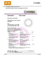
Page 29: ...114 94052 REV H1 29 of 31 8 1 4 Cablena wire size 25mm Datenblatt Cablena Leitungsquerschnitt 25mm...

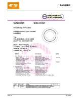
Page 30: ...114 94052 REV H1 30 of 31 8 1 5 Kromberg Schubert wire size 35mm Datenblatt kromberg Schubert Leitungsquerschnitt 35mm...

Page 31: ...114 94052 REV H1 31 of 31...

Reviews: