408-10390
Rev
T
12
of 25
5.
ADJUSTMENTS
5.1.
Adjusting the wire crimp
1. Select an increment number from 0 (largest crimp height) to 150 (smallest crimp height) from the data
plate for the wire size to be used. Each increment represents a change in crimp height of 0.01 mm
[.0004 in.].
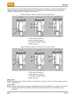
2. Adjust the crimp height by turning the wire crimp height adjustment disc until the required increment
number lines up with the indicator notch on the front of the ram (Figure 12).
Turn the disc clockwise to decrease the crimp height.
Turn the disc counter-clockwise to increase the crimp height.
Figure 12: Wire crimp height adjustment disc
1
Wire crimp disc
2
Indicator notch
3
Insulation crimp dial
3. Adjust the insulation crimp as described in section 5.2.
4. Make several test cycles and inspect the terminations closely. Look for rough or sharp edges around
the crimped barrels (flash), deformed crimps, bent terminals, or other defects caused by worn or
broken tooling. If necessary, replace tooling as described in section 6.
If the terminations appear normal, measure the crimp height of each termination as described in
instruction sheet
, packaged with the applicator. The crimp height must agree with the
measurement specified on the applicator log for the wire size being used. Record crimp height
dimensions for reference.
If the crimp height is incorrect, remove the applicator, and install one that is known to produce
terminations of correct crimp height.
5. Make several test cycles and repeat the inspection.
If the crimp height is incorrect for this applicator, the problem is the machine shut height. Refer to
the appropriate machine manual (Table 1) for corrective measures.
If the crimp height is correct, the problem is in the original applicator, and refer to section 6.8,
Repairing the adjustable crimp height
, for corrective measures.
6. During extensive operation, periodically inspection the terminals as described in step 3 to make sure
that the applicator is producing correct terminations.


