408-10390
Rev
T
2
of 25
2.
DESCRIPTION
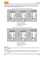
Figure 2 shows the main components of the mechanical feed applicator. Figure 3 shows the main components
of the air feed applicator.
Each applicator is individually designed for specific terminals. The wire crimp height and insulation crimp height
can be adjusted to accommodate different wire sizes and insulation ranges. The applicator is also designed to
accept modular-feed packages.
Figure 2: Mechanical feed applicator
1
Indicator notch / cutout
6
Anvil
11
Drag release lever
2
Ram assembly
7
Wire crimp disc
12
Strip guide block
3
Insulation crimp dial
8
Terminal feeder assembly
13
Strip guide plates
4
Stripper
9
Applicator housing
14
Base plate
5
Lead terminal (for reference)
10
End-feed strip-form terminal strip


