408-10390
Rev
T
5
of 25
2.1.
Applicator with mechanical feed system
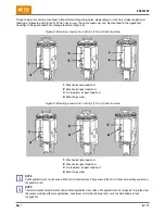
With this applicator (Figure 6), the terminals are fed by the action of the feed cam and a series of rods and
levers that move the feed pawl.
Figure 6: Applicator with mechanical feed system
1
Feed mounting screw (2 places)
6
Stock drag adjustment nuts
11
Feed pawl adjustment screw
2
Stroke pivot
7
Feed pawl pin
12
Applicator counter set screw
3
Stroke length adjustment lock screw
8
Feed pawl holder
13
Spare feed cam storage location
4
Fine feed adjustment screw
9
Feed pawl
5
Fine feed adjustment lock screw
(far side)
10
Applicator counter
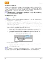
Two feed cams (Figure 7) can be used with the mechanical feed applicator.
The
pre-feed
cam advances the lead terminal over the anvil on the upward stroke of the ram assembly
so that a terminal is over the anvil when the machine is at rest. The pre-feed set up is typically used for
side-feed bench applications.
The
post-feed
cam advances the lead terminal over the anvil on the downward stroke of the ram
assembly. The post-feed set up is typically used for leadmaker and end-feed bench applications.
Figure 7: Mechanical feed cams
1
Pre-feed cam
2
Post-feed cam


