
114-13233
Rev B
12
of 13
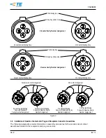
NOTE
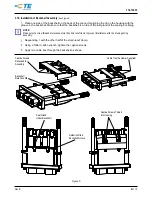
Connector shells must bottom for full engagement and seal compression.
3.20.
Repair/Replacement
CAUTION
Damaged components must not be used. If a damaged component is evident, it must be removed and replaced with a new
one. Terminated contacts and ferrules must not be re-terminated.
4.
QUALIFICATION
Quadrax DSub Connectors and Quadrax Contacts are not required to be agency evaluated and tested.
5.
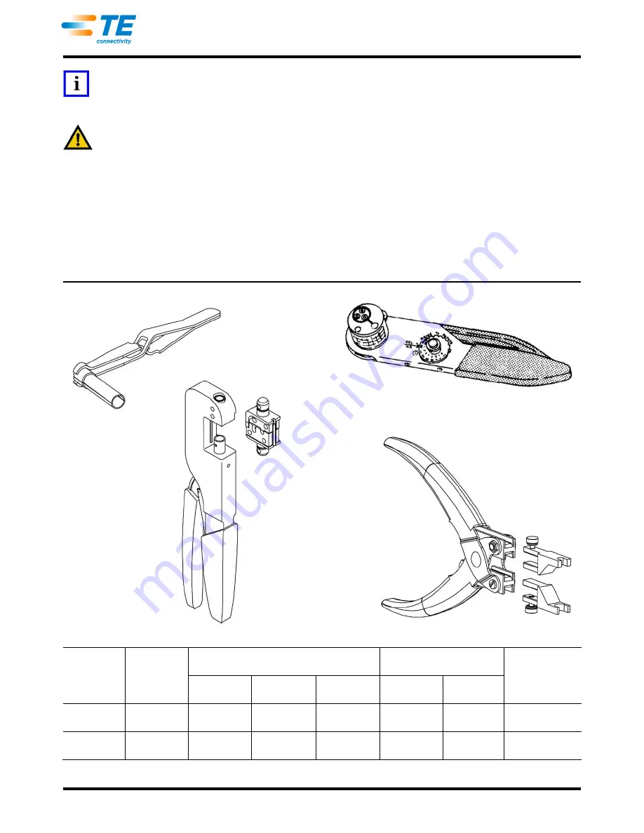
TOOLING
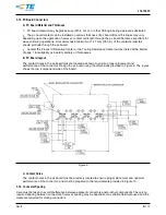
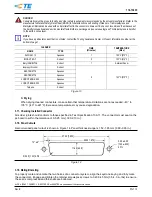
Quadrax Contacts and ferrules can be terminated using hand crimping tools that accommodate the wire size
specified. Military (DANIELS) tool, positioner, and die sets are available to crimp the screw-machine pin or
socket contact, and ferrule. See Figure 15 for recommended tooling.
WIRE SIZE
(AWG)
CONTACT
TYPE
CONTACT TERMINATION TOOLING
FERRULE TERMINATION
TOOLING
RECOMMENDED
EXTRACTION
TOOL
HAND
TOOL
POSITIONER
OR DIE SET
SELECTOR
SETTING
HAND TOOL
DIE SET
26
Pin or Socket
M22520/2-01
K709
4
M22520/5-01
or 608650-1
5-45
1738894-1
24
Pin or Socket
M22520/2-01
K709
5
M22520/5-01
or 608650-1
5-45
1738894-1
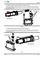
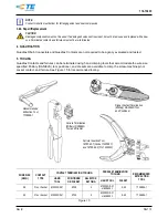
Figure 15
Recommended
Extraction Tool
1738894-1
Ferrule Termination
(Military) DANIELS
Tool and Die Set
Signal Contact Termination
(Military) DANIELS Tool
and Positioner
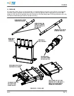
Ferrule Insertion Tool
1976593-1 (Socket 1445693)
and 1976593-2 (Pin 1445692)


