
114-13233
Rev B
3
of 13
Prolonged exposure to ultraviolet light may deteriorate the chemical composition used in the product
material.
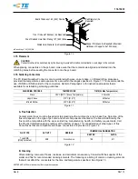
B.
Shelf Life
The contacts and connector kits should remain in the shipping containers until ready for use to prevent
damage. These products should be used on a first in, first out basis to avoid storage contamination.
C.
Chemical Exposure
Do not store product near any chemical listed below as they may cause stress corrosion cracking in the
material.
Alkalies
Ammonia
Citrates
Phosphates Citrates
Sulfur Compounds
Amines
Carbonates
Nitrites
Sulfur Nitrites
Tartrates
NOTE
Where the above environmental conditions exist, phosphor-bronze contacts are recommended if available.
3.4.
Cable Selection and Preparation
Special considerations must be adhered to in the cable stripping operation.
A.
Selection
The pin and socket contacts will accept a wire size of 24 and 26 AWG in a 4-conductor (Quad) cable
configuration in 100 Ohm and 150 Ohm. Cable suppliers such as Raychem* and TENSOLITE may be
used. Contact TE to confirm all cable sizes and compatible contacts.
B.
Preparation
CAUTION
Reasonable care must be taken not to nick, scrape, or cut any conductors during the stripping operation.
NOTE
Dimensions and procedures for stripping the cable may be found on TE Application Specification 114-13123.
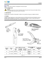
3.5.
Crimped Contact Requirements
NOTE
Dimensions and procedures for crimping the contacts may be found on TE Application Specification 114-13123.
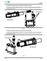
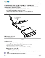
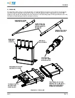
3.6.
Pin Contact Assembly
NOTE
Dimensions and procedures for assembling pin contacts and pin shell may be found on TE Application Specification
114-13123.
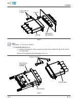
3.7.
Socket Contact Assembly
NOTE
Dimensions and procedures for assembling the socket contacts and socket shell may be found on TE Application Specification
114-13123.
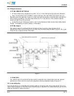
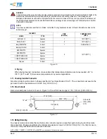
3.8.
Contact Cavity Numbering
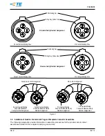
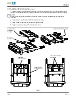
Figure 2 provides information on contact cavity numbering with regards to standard and reverse number
assignments for the pin and socket connector assembly per ARINC 600 Supplement 14.
NOTE
The same specific part number can be used as either a standard or reverse pin assignment. Cavity numbers 2 and 4 are the
same for either standard or reverse assignment. On standard wiring assignment, position 1 will be adjacent to the wiring key
(index line). On reverse assignment, position 3 will be adjacent to the wiring key. Standard verses reverse assignments are
dependent on the location of cavity numbers 1 and 3.
TENSOLITE is a trademark.


