114-13233
Rev B
5
of 13
A.
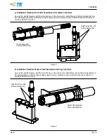
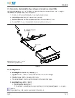
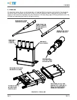
Installation of Quadrax Pin Contact Assemblies in Receptacle Connectors
Line up the positioning key with the internal key on the connector. Install the pin shell sub-assembly into
the receptacle assembly until the pin shell snaps in place. Insert wire seal until flush with rear surface of
housing. Refer to Figure 3.
Figure 3
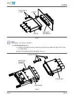
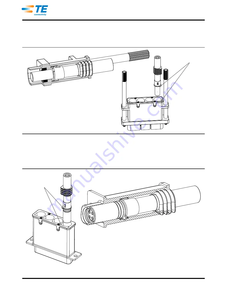
B.
Installation of Quadrax Socket Contact Assemblies into Plug Connectors
Line up the positioning key with the internal key on the connector. Install the socket shell sub-assembly in
the plug assembly until the socket shell snaps in place. Insert wire seal until flush with rear surface of
housing. Refer to Figure 4.
Figure 4
Pin Shell Assembly
Shown with Wire Seal
Align Contact Key with
Internal Housing Key
Socket Shell Assembly
Shown with Wire Seal
Align Contact Key with
Internal Housing Key