background image

114-13233 

Rev B


of 13


3.11.


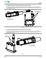
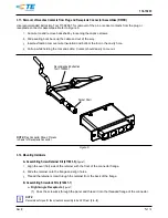
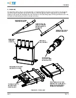
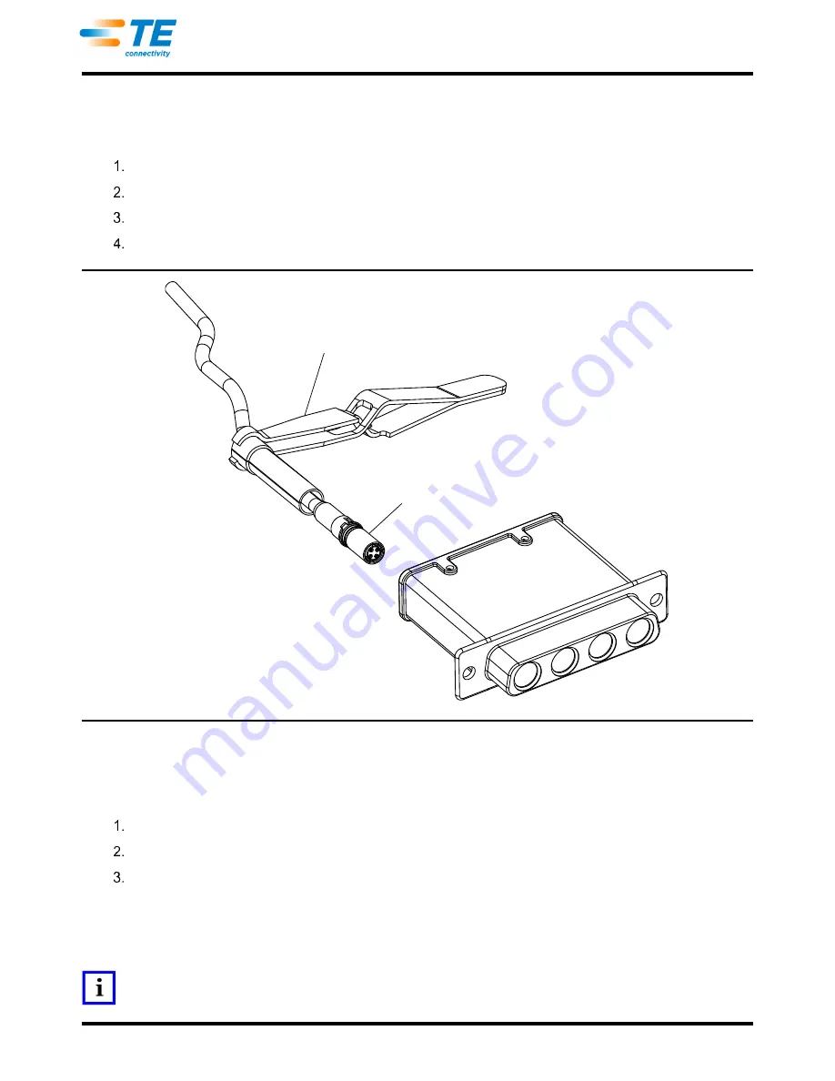
Removal of Quadrax Contacts from Plug and Receptacle Connector Assemblies (RR/RR) 

Use recommended Extraction Tool 1738894-1 for removal of the pin or socket contacts from the plug or 
receptacle connector assemblies. Refer to Figure 6. 

  Cut wire tie and remove backshell by loosening the captive screws. 

  Slide sealing boot back up the cable and out of the way. 

  Insert extraction tool over wire insulation and bottom the tool in the cavity hole. 

  Pull up while holding the tool and cable. Contact should easily come out. 

Figure 6 

3.12.


Mounting Hardware 

A.


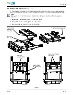
Assembling Screw Retainer Kit (211883-5) 

(Figure 7) 

  Align the oval (flat) side of the retainer with the front of the connector flange. 

  Slide the retainer onto the flange and align holes. 

  Thread the retainer screw through the retainer from the back of the flange. 

B.


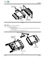
Assembling Screwlock Kits (212447-1) 

a. 

Right-Angle Receptacle


(Figure 7)


(1)  Pass the screwlock through the panel and thread it into the threaded flange of the connector. 

NOTE 

Recommend torque for the screwlock assembly to be 0.45 N●m [4 in.-lb]. 

Socket Shell 

NOTE:

 Plug Connector Shown, Process 

is Same for Receptacle Connector 

Recommended Extraction 

Tool 1738894-1 

Summary of Contents for Quadrax DSub

Page 1: ...g panel mount plug a right angle printed circuit pc board mount receptacle and a free hanging receptacle The Quadrax Pin and Socket Contacts shall be applied to appropriate Quadrax cables The contact...

Page 2: ...d in the manual as a guide for information on soldering problems 2 5 Specifications Product Specification 108 2131 and Qualification Test Report 501 574 provides product performance and test informati...

Page 3: ...must be taken not to nick scrape or cut any conductors during the stripping operation NOTE Dimensions and procedures for stripping the cable may be found on TE Application Specification 114 13123 3 5...

Page 4: ...tandard Cavity Number Assignment Socket Contact Mating Face Pin Contact Mating Face Socket Contact Mating Face Pin Contact Mating Face Positioning Key Wiring Key Index Line Reverse Cavity Number Assig...

Page 5: ...Refer to Figure 3 Figure 3 B Installation of Quadrax Socket Contact Assemblies into Plug Connectors Line up the positioning key with the internal key on the connector Install the socket shell sub ass...

Page 6: ...Make sure the screw threads are recessed into the strain relief clamp to prevent interference with the housing during assembly Repeat step 1 with the other half of the strain relief clamp Using a 5 64...

Page 7: ...tool and cable Contact should easily come out Figure 6 3 12 Mounting Hardware A Assembling Screw Retainer Kit 211883 5 Figure 7 Align the oval flat side of the retainer with the front of the connecto...

Page 8: ...washers on the screwlock and insert the screwlock through the front of the connector flange 2 Secure the assembly with a lockwasher and a nut Figure 8 Screw Retainer Kit 211883 5 Screwlock Right Angl...

Page 9: ...of page 1 for suitability pc board materials or thicknesses B PC Board Layout The contact holes in the pc board must be located as shown to ensure proper placement and performance of the connector De...

Page 10: ...rosin base flux Selection of the flux will depend on the type of pc board and other components mounted on the board Additionally the flux must be compatible with the wave solder line manufacturing he...

Page 11: ...C 212 F KESTER 5778 Aqueous KESTER 5779 Aqueous LONCOTERGE 520 Aqueous LONCOTERGE 530 Aqueous Terpene Solvent Figure 13 C Drying When drying cleaned connectors make certain that temperature limitatio...

Page 12: ...pecified Military DANIELS tool positioner and die sets are available to crimp the screw machine pin or socket contact and ferrule See Figure 15 for recommended tooling WIRE SIZE AWG CONTACT TYPE CONTA...

Page 13: ...his specification and in the instructional material shipped with the product or tooling FIGURE 16 VISUAL AID WIRE MUST BE VISIBLE IN INSPECTION HOLE CONTACT MUST BE VISUALLY STRAIGHT AND NO DAMAGE TO...

Reviews: