
114-13233
Rev B
9
of 13
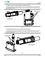
3.13.
PC Board Connectors
A.
PC Board Material and Thickness
PC board material may be glass epoxy (FR-4, G-10), or other TE Engineering approved substrates.
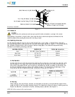
The pc board contact can be installed on various thickness of pc board. Board thickness may vary
depending upon the application, however, contact tail length through the pc board becomes important for
wave soldering operations. A recommended minimum of 1.27 mm [.050 in.] of the contact solder tail
should protrude through the pc board.
Contact the Product Information Center or the Tooling Assistance Center number listed at the bottom
of page 1 for suitability pc board materials or thicknesses.
B.
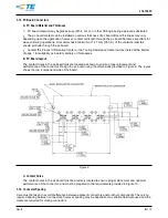
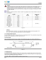
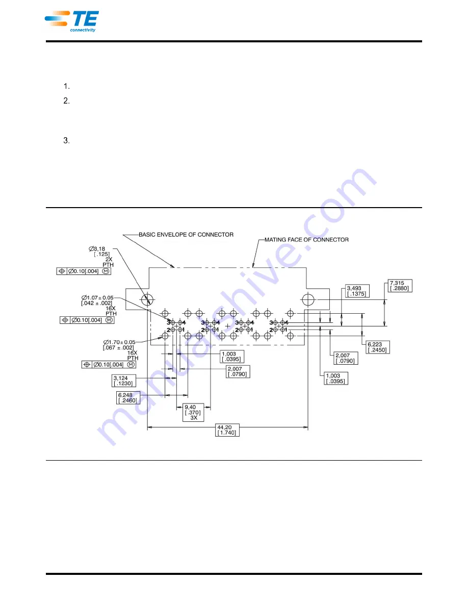
PC Board Layout
The contact holes in the pc board must be located as shown to ensure proper placement and
performance of the connector. Design the pc board using the dimensions provided in Figure 9. The layout
shows the top (component) side of the board.
Figure 9
C.
Contact Holes
The contact holes in the pc board must be precisely located to ensure proper placement and optimum
performance of the connector, and must be prepared to the requirements provided in Figure 10.
3.14.
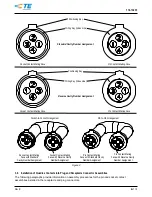
Connector Spacing
Care must be taken to avoid interference between adjacent connectors and/or other components. There is no
required spacing between connectors, however spacing may be dependent on variable hardware used and the
clearance required for mating connectors.


