

Raychem Devices
No: RCPS-200-20
Rev: E1
Date: August 10, 2016
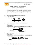
Installation Procedures for D-436-XX and D-200-XX
(Miniseal™) Sealed Crimp Splices
_________________________________________
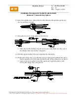
Unless otherwise specified dimensions are in millimeters. [Inches dimensions are in between brackets]
© 2007-2016 TE Connectivity Corporation. All rights reserved.
If this document is printed it becomes uncontrolled. Check for the latest revision.
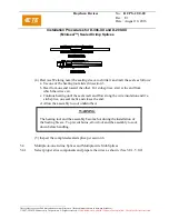
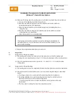
(3) The sealing sleeve must not be discolored to the point where it prevents visual
inspection of the splice (overheated condition).
6.3
Inspection for Damage
(1) The sealing sleeve must not be cut or split.
(2) The wire insulation must not show signs of mechanical damage or overheating, such
as cuts, tears, melting, charring.
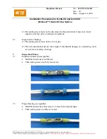
7.
Inspection Photos:
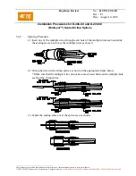
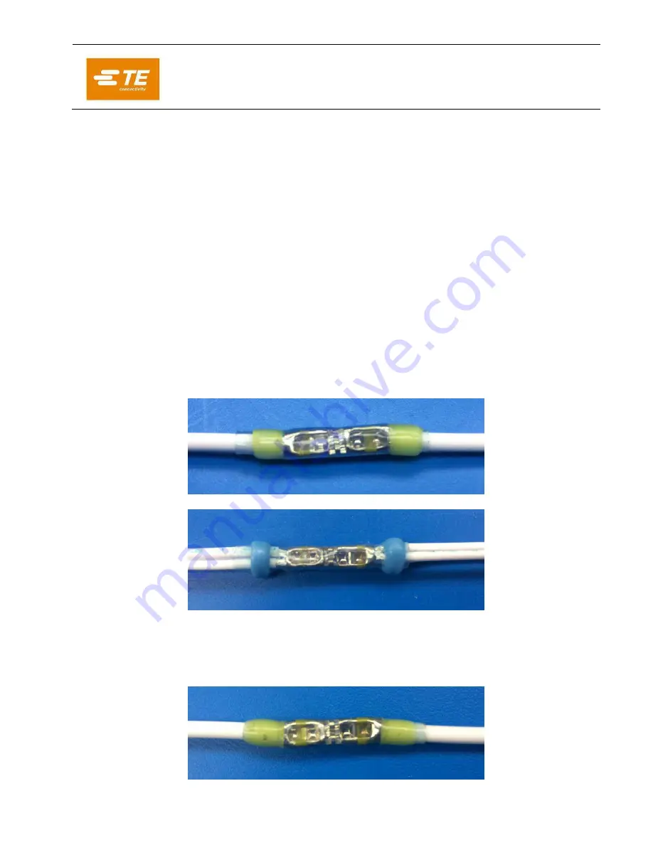
7.1
Insufficient Heat (Unacceptable)
Meltable Inserts have not flowed
Then sealing sleeve not fully recovered
7.2
Proper Heating (Acceptable)
Meltable Inserts have flowed so as to lose their original shape
Then sealing sleeve is fully recovered


