Raychem Devices
No: RCPS-200-20
Rev: E1
Date: August 10, 2016
Installation Procedures for D-436-XX and D-200-XX
(Miniseal™) Sealed Crimp Splices
_________________________________________
Unless otherwise specified dimensions are in millimeters. [Inches dimensions are in between brackets]
© 2007-2016 TE Connectivity Corporation. All rights reserved.
If this document is printed it becomes uncontrolled. Check for the latest revision.
4.2
Applications
The sealing sleeves covered by this document are designed for immersion resistant splice
sealing when no more than one wire is inserted through each hole of the seals. In some
instances a maximum of two wires of specified sizes can be inserted through each hole of
the seals, with factory evaluation and approval.
5.
Procedure:
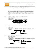
These procedures are for installing crimp splices and sealing sleeves of the D-436-XX
and D-200-XX series. Separate procedures are provided for parts conforming to
paragraphs 4.1.1, 4.1.2, and 4.1.3.
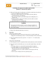
WARNING
Follow installation instructions carefully. Use adequate ventilation and
avoid charring or burning during installation. Charring or burning the
product will produce fumes that may cause eye, skin, nose and throat
irritation. Consult Material Safety Data Sheets RAY5106 for further
information.
5.1
Part Selection
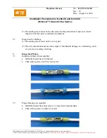
Select the proper splice components for the application according to the applicable
drawing or to the Selection Guide, or Customer Drawings (CD). See section 2.
5.2
Wire Preparation
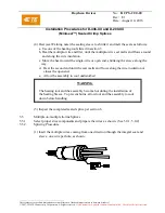
(1) Strip the wires to be spliced. If any conductor is to be folded back to increase the
effective cross-sectional area, strip that wire to twice the specified strip length.
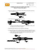
Strip lengths:
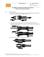
The strip length for a particular crimp splice equals the length of the crimp barrel plus
0.8 - 1.6 mm (1/32
–
1/16 inch) See figure on next page.
For most AWG 12 and smaller crimp splices, the correct strip length is
7.9 - 8.7 mm (5/16 - 11/32 inch).


