background image


Raychem Devices 

No:    RCPS-200-20 
Rev:   E1 
Date:  August 10, 2016 

Installation Procedures for D-436-XX and D-200-XX 

(Miniseal™) Sealed Crimp Splices


_________________________________________ 
Unless otherwise specified dimensions are in millimeters.  [Inches dimensions are in between brackets] 
© 2007-2016 TE Connectivity Corporation.  All rights reserved.  

If this document is printed it becomes uncontrolled.  Check for the latest revision.


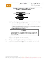
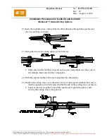
(4) Heat (see Warning note) the sealing sleeve to shrink it and melt the seals as follows: 

a. Use one of the heating tools listed in section 3. 
b. Heat the multiple-wire end first, until the multiple-wire seal melts and flows around 

and along the wire insulation. 

c. Move the heat toward the single-wire or open end, shrinking the sleeve along the 

way. 

d.  Heat the second end until the seal melts and flows along the wire insulation or


closes the open end. 

e.  Allow the assembly to cool undisturbed. 
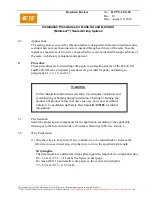
 

WARNING 


The heating tool and the assembly become hot during the installation of 


the Sealing Sleeve. To prevent burns, allow tool and the assembly to cool 


down before handling. 


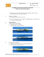
(5) Inspect the completed sealed splice per section 6. 
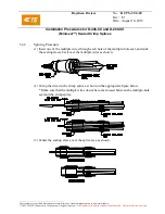
 
5.5 

Multiple-to-multiple In-line Splices 

5.5.1. 

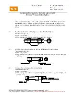
Select proper slice components and prepare the wires as shown. (See 5.0.1, 5.0.2) 

5.5.2. 

Splicing Procedure 


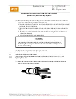
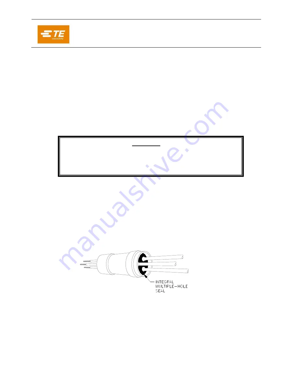
(1) Insert the multiple wires coming from one direction through the integral seal and 


sleeve, one wire per hole, as shown. 


Summary of Contents for RAYCHEM D-436 Series

Page 1: ...3 Application Equipment and Tools 3 1 Crimp Tools 1 AD 1377 Crimp Tool 2 Manufacturer s recommended crimp tool for splices other than Tyco Electronics Raychem crimp splices 3 2 Heating Tools Products...

Page 2: ...upplied in three basic configurations according to the number of wires that can be spliced together These part and splice configurations are as follows 4 1 1 One Wire to One Wire In Line Splices or Tw...

Page 3: ...he D 436 XX and D 200 XX series Separate procedures are provided for parts conforming to paragraphs 4 1 1 4 1 2 and 4 1 3 WARNING Follow installation instructions carefully Use adequate ventilation an...

Page 4: ...n the splicing tables to fold any conductors back fold the appropriate conductor s as shown below 5 3 One to one In line Splices and Two wire Stub Splices 5 3 1 Select proper slice components and prep...

Page 5: ...lows a Use one of the heating tools listed in section 3 b Heat from one end toward the other For stub splices start at the end from which the wires exit c Continue heating until the seals melt and flo...

Page 6: ...All rights reserved If this document is printed it becomes uncontrolled Check for the latest revision 5 4 2 Splicing Procedure 1 Insert one of the multiple wires through each hole of the multiple hole...

Page 7: ...the multiple wire seal melts and flows around and along the wire insulation c Move the heat toward the single wire or open end shrinking the sleeve along the way d Heat the second end until the seal m...

Page 8: ...ltiple wires coming from the other direction through the separate seal one wire per hole as shown 3 Crimp the wires in the crimp splice as shown below Make sure that the multiple wires do not become c...

Page 9: ...sturbed WARNING The heating tool and the assembly become hot during the installation of the Sealing Sleeve To prevent burns allow tool and the assembly to cool down before handling 7 Inspect the compl...

Page 10: ...r the latest revision 3 The sealing sleeve must not be discolored to the point where it prevents visual inspection of the splice overheated condition 6 3 Inspection for Damage 1 The sealing sleeve mus...

Page 11: ...tears melting charring 1 These values are for reference only and may change based on other variables i e reflector type sleeve s relative distance to the reflector etc DISCLAIMER All of the above inf...

Reviews: