background image

EPP-1988-INT-7/13      15/20

FR

;;;;;;;;;;;;;

;;;;;;;;;;;;;

;;;;;;;;;;;;;

;;;;;;;;;;;;;

6 W

8 W

;;;;;;;;;;;;;;;;;

;;;;;;;;;;;;;;;;;

;;;;;;;;;;;;;;;;;

;;;;;;;;;;;;;;;;;

;

;

;

;

;

;

;

;

;

;

;

;

;

;

;

;

;

;

;

;

;

;

;

;

;

;

7 W

Marking line

Joint completed.

Allow the joint to cool before applying any mechanical strain.

OPTION S: 

Installation using 

Outer Seeling Sleeve

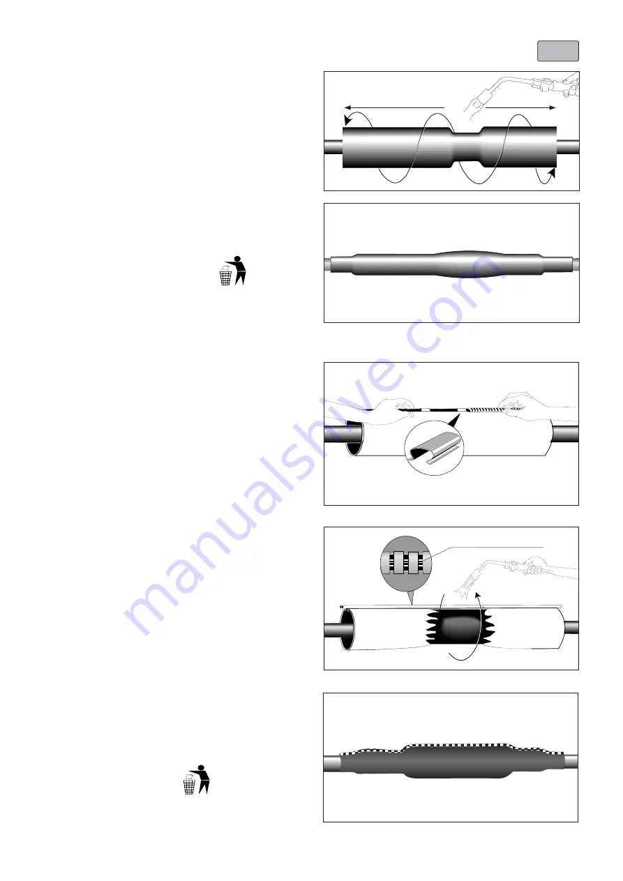
Clean the cable jackets on both cable ends and abrade them 
for a distance of at least 150 mm.

Position the outer sealing sleeve centrally over the joint area. 
Control the equal overlap on both cable jackets.

Shrink down the outer sealing sleeve, starting over the 
connector area (outside the center), working towards the 
ends.

OPTION W: 

Installation using 

Wraparound Joint Sleeve

Clean and degrease 150 mm of the oversheath on the plastic 
cable end.

Remove the inner protective plastic and position the 
wraparound joint sleeve centrally over the joint covering the 
oversheath to the same extent on both cable sides.

Press the retention clips over the rail of the wraparound to 
keep it in place.

Push the metal channels over the rail of the wraparound.The 
end of the metal channel should butt up and equally overlap 
the retention clips.

After all channels have been pushed on they should overlap 
the wraparound equally on both sides.

Please dispose of all waste 
according to environmental 
regulations.

Joint completed.

Allow the joint to cool before applying any mechanical strain.

Please dispose of all waste 
according to environmental 
regulations.

Shrink the wraparound sleeve into place starting at the 
middle of the joint. When the colour of the paint on the 
wraparound has completely changed to black progressively 
move towards the ends.

Note: 

Extra heat is required on the metal channel. Heat until 

the marking line (white) on the rails can be seen under the 
channels.

Place metal ZIP along the cable core, this will support the 
ZIP when heating.

6 S

7 S

Summary of Contents for Raychem LJSM Series

Page 1: ...sulated cables without armour Joint types LJSM B 4X LJSM B 5X Revision Juli 2013 EN Tyco Electronics Raychem GmbH a TE Connectivity Ltd Company TE Energy Finsinger Feld 1 85521 Ottobrunn Munich German...

Page 2: ...harp knife leaving no jagged edges Start shrinking the tubing at the position recommended in the instruction Ensure that the tubing is shrunk smoothly all around before continuing along the cable Tubi...

Page 3: ...he reference line Cut back the core insulation on all cores to I half connector length 150 a b l l 150 A Reference line Cable jacket Insulation Reference line cut remove Table 1 Dimensions according t...

Page 4: ...red sector shaped cores have to be turned to the outside Conductor connection Wire brush the aluminium conductors Hand tighten the shear bolts so that the connector stays in place For connectors using...

Page 5: ...extent on both cable sides Press the retention clips over the rail of the wraparound to keep it in place Push the metal channels over the rail of the wraparound The end of the metal channel should bu...

Page 6: ...eradrige und f nfadrige kunststoffisolierte Kabel 1 kV ohne Bewehrung Typen LJSM B 4X LJSM B 5X Revision Juli 2013 Tyco Electronics Raychem GmbH ein Unternehmen der TE Connectivity Gruppe TE Energy Fi...

Page 7: ...erstellers ist zu beachten Schl uche und Formteile gem den gesonderten Anweisungen innerhalb der Montagefolge aufschieben bzw schrumpfen Schl uche und Formteile m ssen rundum fest und faltenfrei anlie...

Page 8: ...esetzten Kabelseite kreuzen Anschlie end die Adern an der Bezugslinie schneiden Absetzma e der Leiterisolierung F r alle Kabeladern I halbe Verbinderl nge a b l l 150 A Kabelmantel Isolierung Bezugsli...

Page 9: ...r nach au en ausgedreht werden Leiter mit einer Stahlb rste b rsten Schraubverbinder auf den abgesetzten Leitern parken Abscherschrauben handfest anziehen so dass der Verbinder fixiert ist Bei Verbind...

Page 10: ...n und entfetten Faserverst rkte Schrumpfmanschette mittig ber der Muffe positionieren so dass die Kabelm ntel auf beiden Seiten gleich weit abgedeckt werden Manschette mit Verbindungsklammer zusammenf...

Page 11: ...Feld 1 85521 Ottobrunn Munich Germany Tel 49 89 6089 0 Fax 49 89 6096 345 energy te com Instruction de montage EPP 1988 INT 7 13 Jonction basse tension Raychem avec raccords vis pour c ble polymerique...

Page 12: ...es du fabricant si vous utilisez du solvent Retreindre les pi ces en commen ant sur la position prescrite dans l instruction de montage Retreindre les pi ces uniform ment sur toute la circonf rence av...

Page 13: ...per les mes sur la ligne de r f rence et enlever l isolant sur la moiti de la longueur du raccord vis a b l l 150 A Gaine ext rieure Isolant ligne de r f rence couper d nuder FR 150 ligne de r f rence...

Page 14: ...on du raccord vis Brosser les mes en aluminium avec une brosse en acier Serrer les vis la main jusqu ce que les raccords restent en place Serrer les vis jusqu ce qu elles cassent pour des raccords ave...

Page 15: ...extent on both cable sides Press the retention clips over the rail of the wraparound to keep it in place Push the metal channels over the rail of the wraparound The end of the metal channel should bu...

Page 16: ...gmof met schroef verbinders voor 4 en 5 polige kuststofkabel zonder wapening Mof types LJSM B 4X LJSM B 5X Revisie Juli 2013 Tyco Electronics Raychem GmbH a TE Connectivity Ltd Company TE Energy Finsi...

Page 17: ...smiddel Krimp de stukken te beginnen bij de opgegeven plaats in de installatie instructie Zorg ervoor dat de stukken gelijkmatig gekrompen worden De krimpkousen moeten na installatie glad en zonder ri...

Page 18: ...n de lange aders Snijd de aders door op de referentielijn en verwijder de isolatie over de halve lengte van de verbinder 150 a b l l 150 A Referentielijn Buitenmantel Isolatie Referentielijn snijd ver...

Page 19: ...binder Borstel aluminium geleiders met een staalborstel Schroef de bouten aan met de hand tot de verbinder op zijn plaats blijft zitten Span de bouten verder aan tot ze afbreken voor verbinders met me...

Page 20: ...extent on both cable sides Press the retention clips over the rail of the wraparound to keep it in place Push the metal channels over the rail of the wraparound The end of the metal channel should bu...

Reviews: