EPP-1988-INT-7/13 5/20
EN
;;;;;;;;;;;;;
;;;;;;;;;;;;;
;;;;;;;;;;;;;
;;;;;;;;;;;;;
6 W
8 W
;;;;;;;;;;;;;;;;;
;;;;;;;;;;;;;;;;;
;;;;;;;;;;;;;;;;;
;;;;;;;;;;;;;;;;;
;
;
;
;
;
;
;
;
;
;
;
;
;
;
;
;
;
;
;
;
;
;
;
;
;
;
7 W
Marking line
Joint completed.
Allow the joint to cool before applying any mechanical strain.
OPTION S:
Installation using
Outer Seeling Sleeve
Clean the cable jackets on both cable ends and abrade them
for a distance of at least 150 mm.
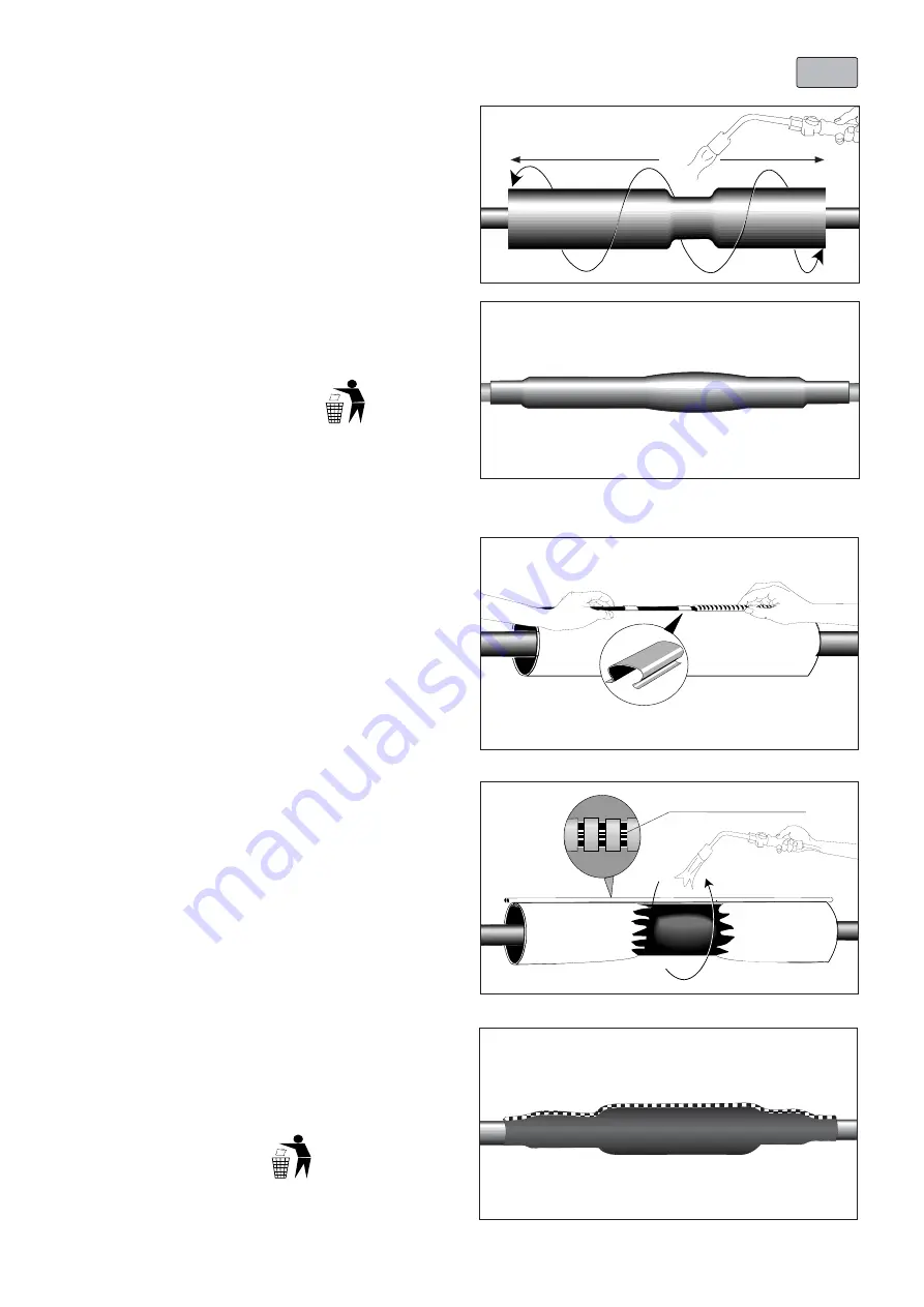
Position the outer sealing sleeve centrally over the joint area.
Control the equal overlap on both cable jackets.
Shrink down the outer sealing sleeve, starting over the
connector area (outside the center), working towards the
ends.
OPTION W:
Installation using
Wraparound Joint Sleeve
Clean and degrease 150 mm of the oversheath on the plastic
cable end.
Remove the inner protective plastic and position the
wraparound joint sleeve centrally over the joint covering the
oversheath to the same extent on both cable sides.
Press the retention clips over the rail of the wraparound to
keep it in place.
Push the metal channels over the rail of the wraparound.The
end of the metal channel should butt up and equally overlap
the retention clips.
After all channels have been pushed on they should overlap
the wraparound equally on both sides.
Please dispose of all waste
according to environmental
regulations.
Joint completed.
Allow the joint to cool before applying any mechanical strain.
Please dispose of all waste
according to environmental
regulations.
Shrink the wraparound sleeve into place starting at the
middle of the joint. When the colour of the paint on the
wraparound has completely changed to black progressively
move towards the ends.
Note:
Extra heat is required on the metal channel. Heat until
the marking line (white) on the rails can be seen under the
channels.
Place metal ZIP along the cable core, this will support the
ZIP when heating.
6 S
7 S


