background image


Tyco Electronics Corporation 
300 Constitutional Drive 
Menlo Park, CA 94025 USA


No:    RPIP-824-00 
Rev:   F 
Date:  April 28, 2006 
Page: 10 of 11 

© 2005-2006 Tyco Electronics Corporation. All rights reserved. 

Unless otherwise specified dimensions are in millimeters [Inches dimensions are in between brackets] 

If this document is printed it becomes uncontrolled.  Check for the latest revision.


4.5.2 Assembly 

1.  Overlap the exposed conductor and the component pin and position the CWT-200X-A  
 

or B-155-200X-A sub-assembly so that the solder preform is centered over the conductors. 

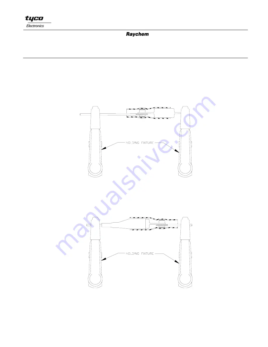
2.  Use a holder to keep the wire and component aligned during heating. 
3.  Heat solder preform until it melts and forms a fillet between the conductors. 


4.  Overlap the other exposed conductor and component pin and position the CWT-200X-B 

or B-155-200X-B sub-assembly so the solder preform is centered over the conductors. 

5.  Use a holder to keep the wire and component aligned during heating. 
6.  Heat solder preform until it melts and forms a fillet between the conductors. 


Summary of Contents for SolderSleeve B-155 1000 Series

Page 1: ...d termination The one piece design of one step terminators simplifies installation while their transparent insulation sleeves make inspection easy 2 0 Application Equipment Equivalent tools may be use...

Page 2: ...efore handling 4 1 Shield Terminations 4 1 1 Cable Preparation 1 Remove length specified in Table I of the cable jacket at the point where the termination is to be made A Center Stripped A AS REQUIRED...

Page 3: ...354 11 13 0 0 512 12 0 0 472 10 0 0 394 B 155 XX B 155 XX 1000 B 155 XX 35 22 5 B 155 XX 35 22 9 CWT XX CWT XX 1000 CWT XX W122 5 CWT XX W122 9 13 17 0 0 670 16 0 0 630 14 0 0 551 3 5 7 0 0 276 6 0 0...

Page 4: ...revision Unacceptable Insufficient heat Contour of solder perform is visible Acceptable Fillet is clearly visible between the lead and shield 4 2 Wire to Wire In Line Splices 4 2 1 Wire Preparation 1...

Page 5: ...cal attachment is required secure the 2 wire ends by twisting them together Align carefully the strands in order to avoid any poke through of the sleeve See Fig 1 and Fig 2 In other cases align wires...

Page 6: ...sible and a solder fillet at least 4 5 0 180 long should be visible on one side of the leads Fillet length should be 8 0 0 315 for 12 5 0 500 stripped wires Lack of solder fillet may indicate overheat...

Page 7: ...ly 1 Position the smaller or center conductor one step terminator so that the end is against the folded shield and the solder preform is visually centered over the exposed center conductor 2 Heat sold...

Page 8: ...WG 1 5mm2 and larger 1 Trim terminal lead to 11 0 1 5 0 435 0 060 2 Remove 9 5 0 375 of wire insulation 3 Pre tin conductors 4 4 3 Assembly 1 Position the one step terminator over the connector termin...

Page 9: ...ible and a solder fillet at least 4 5 0 180 long should be visible on one side of the leads Fillet length should 8 0 0 315 for larger wires Lack of a solder fillet may indicate overheating 3 Damage Th...

Page 10: ...onductor and the component pin and position the CWT 200X A or B 155 200X A sub assembly so that the solder preform is centered over the conductors 2 Use a holder to keep the wire and component aligned...

Page 11: ...rands should poke through the sleeve Fillet length should be 8 0 0 315 for 12 5 0 500 stripped wires Unacceptable Insufficient heat Contour of solder perform is visible Acceptable Solder has lost all...

Reviews: