background image


Tyco Electronics Corporation 
300 Constitutional Drive 
Menlo Park, CA 94025 USA


No:    RPIP-824-00 
Rev:   F 
Date:  April 28, 2006 
Page: 2 of 11 

© 2005-2006 Tyco Electronics Corporation. All rights reserved. 

Unless otherwise specified dimensions are in millimeters [Inches dimensions are in between brackets] 

If this document is printed it becomes uncontrolled.  Check for the latest revision.


WARNING 


The heating tool and the assembly become hot during the installation of 


the SolderSleeve One-Step Wire and Cable Terminators. To prevent burns,  


allow tool and the assembly to cool down before handling. 


4.1 Shield 

Terminations 

 
4.1.1 Cable 

Preparation 


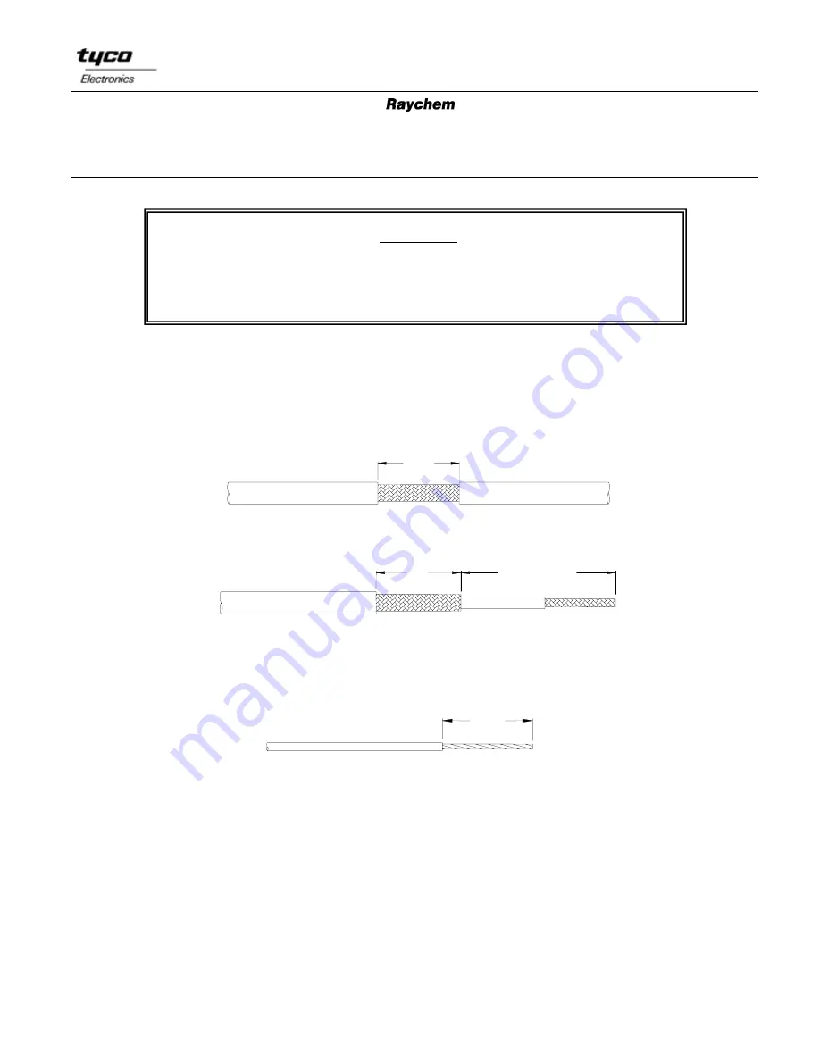
1. Remove length specified in Table I of the cable  jacket at the point where the termination is 

to be made. 


Center Stripped 


A                              AS REQUIRED


End Stripped


2. Remove length specified in Table I of insulation from the end of the ground lead. (If part 

has pre-installed lead, omit this step.) 


4.1.2 Assembly 


1. Position the one-step soldersleeve shield terminator so that the solder preform is centered 

over the exposed shield.  

2. Position the lead to be attached between the solder and the exposed shield. 
3. Allow the application equipment to reach the operating temperature. 
4. Place the assembly centrally in the reflector. 
5. Heat the solder preform until it melts and forms a fillet between the lead and the shield. 

Summary of Contents for SolderSleeve B-155 1000 Series

Page 1: ...d termination The one piece design of one step terminators simplifies installation while their transparent insulation sleeves make inspection easy 2 0 Application Equipment Equivalent tools may be use...

Page 2: ...efore handling 4 1 Shield Terminations 4 1 1 Cable Preparation 1 Remove length specified in Table I of the cable jacket at the point where the termination is to be made A Center Stripped A AS REQUIRED...

Page 3: ...354 11 13 0 0 512 12 0 0 472 10 0 0 394 B 155 XX B 155 XX 1000 B 155 XX 35 22 5 B 155 XX 35 22 9 CWT XX CWT XX 1000 CWT XX W122 5 CWT XX W122 9 13 17 0 0 670 16 0 0 630 14 0 0 551 3 5 7 0 0 276 6 0 0...

Page 4: ...revision Unacceptable Insufficient heat Contour of solder perform is visible Acceptable Fillet is clearly visible between the lead and shield 4 2 Wire to Wire In Line Splices 4 2 1 Wire Preparation 1...

Page 5: ...cal attachment is required secure the 2 wire ends by twisting them together Align carefully the strands in order to avoid any poke through of the sleeve See Fig 1 and Fig 2 In other cases align wires...

Page 6: ...sible and a solder fillet at least 4 5 0 180 long should be visible on one side of the leads Fillet length should be 8 0 0 315 for 12 5 0 500 stripped wires Lack of solder fillet may indicate overheat...

Page 7: ...ly 1 Position the smaller or center conductor one step terminator so that the end is against the folded shield and the solder preform is visually centered over the exposed center conductor 2 Heat sold...

Page 8: ...WG 1 5mm2 and larger 1 Trim terminal lead to 11 0 1 5 0 435 0 060 2 Remove 9 5 0 375 of wire insulation 3 Pre tin conductors 4 4 3 Assembly 1 Position the one step terminator over the connector termin...

Page 9: ...ible and a solder fillet at least 4 5 0 180 long should be visible on one side of the leads Fillet length should 8 0 0 315 for larger wires Lack of a solder fillet may indicate overheating 3 Damage Th...

Page 10: ...onductor and the component pin and position the CWT 200X A or B 155 200X A sub assembly so that the solder preform is centered over the conductors 2 Use a holder to keep the wire and component aligned...

Page 11: ...rands should poke through the sleeve Fillet length should be 8 0 0 315 for 12 5 0 500 stripped wires Unacceptable Insufficient heat Contour of solder perform is visible Acceptable Solder has lost all...

Reviews: