Tyco Electronics Corporation
300 Constitutional Drive
Menlo Park, CA 94025 USA
No: RPIP-824-00
Rev: F
Date: April 28, 2006
Page: 8 of 11
© 2005-2006 Tyco Electronics Corporation. All rights reserved.
Unless otherwise specified dimensions are in millimeters [Inches dimensions are in between brackets]
If this document is printed it becomes uncontrolled. Check for the latest revision.
4.4.2 Wire
Preparation
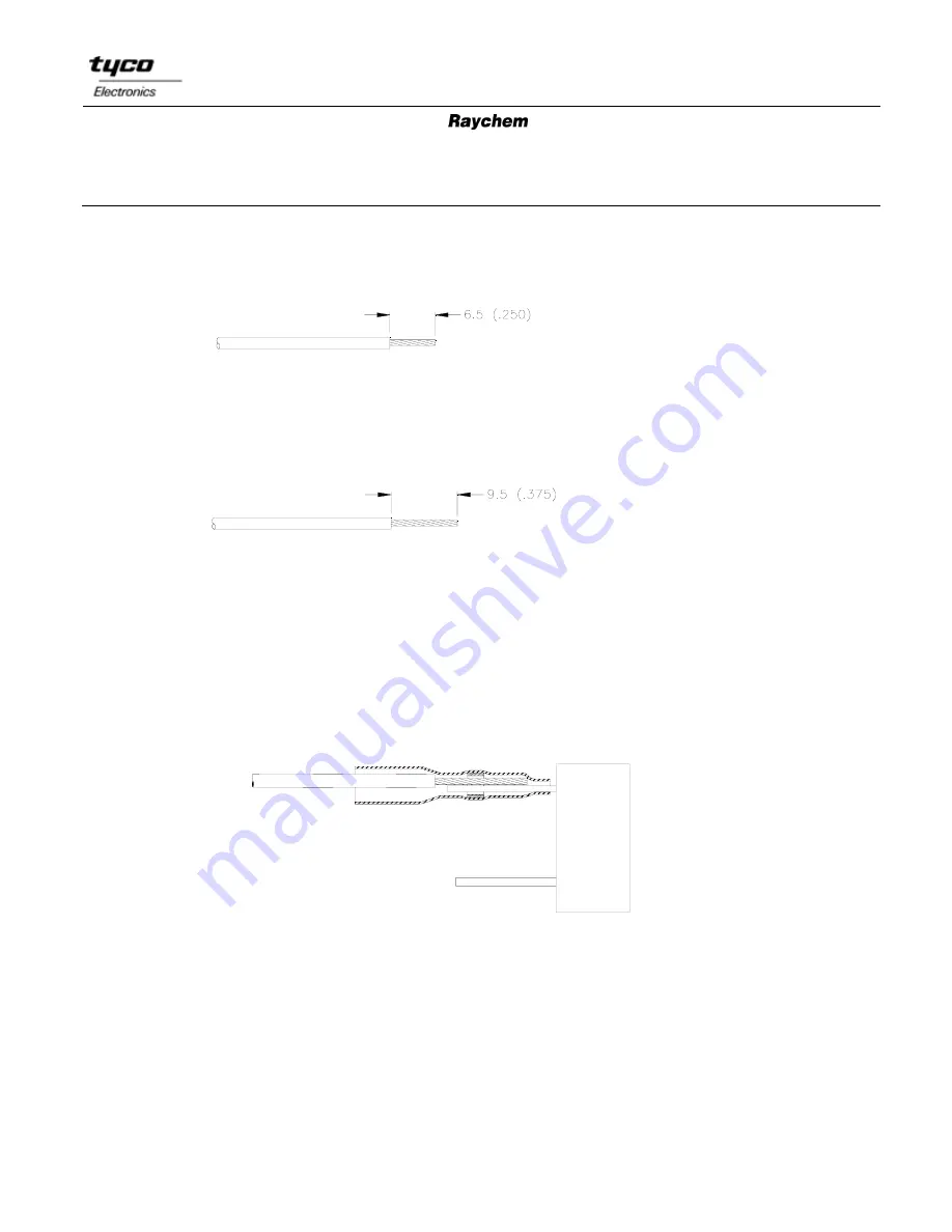
A: Wires smaller than 18 AWG [1.5mm
2
]
1.
Trim terminal/lead to 8.0±1.5 [0.315±0.060].
2.
Remove 6.5 [0.250] of wire insulation.
3.
Pre-tin conductors if more than 19 strands.
B: Wires 18 AWG [1.5mm
2
] and larger
1. Trim terminal/lead to 11.0 ±1.5 [0.435±0.060].
2. Remove 9.5 [0.375] of wire insulation.
3. Pre-tin conductors.
4.4.3 Assembly
1.
Position the one-step terminator over the connector terminal or component lead so that the
necked down end is against the connector or component. The solder preform must not
extend beyond the terminal/lead end.
2.
Insert the wire to be attached so that it bottoms against the step in the sleeve. The wire
insulation must end between the top of the terminal and the end of the sleeve.
3.
Heat solder preform until it melts and forms a fillet between the wire and the terminal.
4.4.4 Inspection
1.
Positioning: 18 AWG [1.5mm
2
] conductor should overlap the terminal/lead at least
4.5 [0.180]. Larger wires should overlap at least 5/16 in [8 mm].


