31
6.0
Data Acquisition Features
6.1
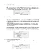
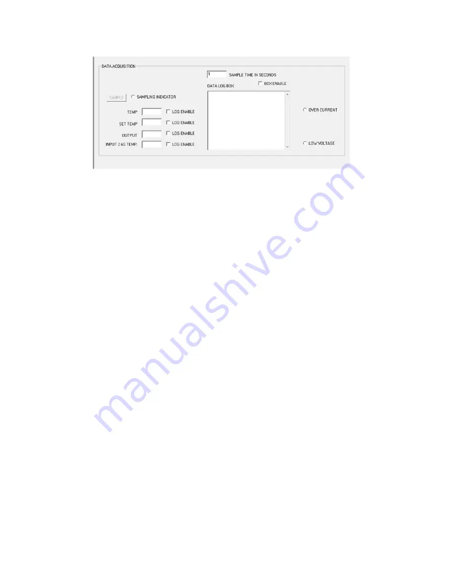
SAMPLE button:
Clicking the sample button instructs the controller to report the controller operating conditions for TEMP, SET
TEMP, OUTPUT, INPUT2 AS TEMP, and OVER CURRENT COUNT.
6.2
SAMPLE TIME IN SECONDS box:
Enter the time, in seconds. This sets the controller update interval for the various operating conditions.
6.3
TEMP box:
This shows the temperature currently being sensed by the primary thermistor.
6.4
SET TEMP box:
This simply reports what was entered in the FIXED SET TEMP. box.
6.5
OUTPUT box:
This indicates the percentage of power (duty cycle) being applied to the TE device.
6.6
INPUT2 AS TEMP box:
This shows the temperature of the secondary thermistor if it is installed.
6.7
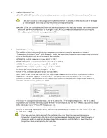
LOG ENABLE check box:
If the box is unchecked, the controller will not save any previous data reported to software.
If the box is checked, the controller will report the data to the DATA LOG BOX before updating at the next sample
time interval.
6.8
DATA LOG BOX:
If any of the sample boxes have the LOG ENABLE box checked, the data from those boxes will be recorded to the
DATA LOG BOX at each time interval. Be sure that the BOX ENABLE box is checked. The data does scroll down and
off of the screen. However, you can cut and paste it into a spreadsheet if necessary.
6.9
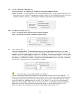
OVER CURRENT indicator:
This indicator shows when the controller has shut the output off because of an over current condition.
6.10
LOW VOLTAGE indicator:
This indicator shows when the output driver circuitry has turned the output MOSFETs off due to a low controller
circuit voltage. The output will be turned off if the controller circuit voltage drops below approximately 11.0 to
11.2 volts. The output will automatically restart when the voltage increases to approximately 11.4 volts. This is a
hardware based function safety function and cannot be overridden by software settings.


