background image


58 

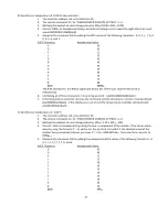
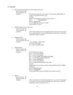
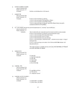
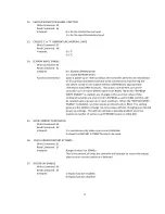
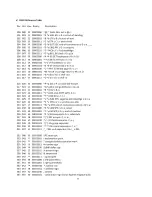
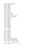
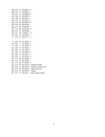
TS-141 Temperature (°C) versus Resistance (ohms, Ω) Data 

for MP-3716


TS-91 Temperature (°C) versus Resistance (ohms, Ω) Data 


-40

168300

-19

45830

2

14750

23

5460

44

2272

65

1041

-39

157500

-18

43270

3

14030

24

5225

45

2184

66

1006

-38

147500

-17

40860

4

13340

25

5000

46

2101

67

971

-37

138200

-16

38610

5

12700

26

4787

47

2021

68

938

-36

129500

-15

36490

6

12090

27

4583

48

1944

69

906.5

-35

121400

-14

34500

7

11510

28

4389

49

1871

70

875.5

-34

113900

-13

32630

8

10960

29

4204

50

1801

-33

106900

-12

30880

9

10440

30

4029

51

1734

-32

100300

-11

29230

10

9950

31

3861

52

1670

-31

94200

-10

27670

11

9485

32

3702

53

1608

-30

88500

-9

26210

12

9045

33

3549

54

1549

-29

83200

-8

24830

13

8630

34

3404

55

1493

-28

78250

-7

23540

14

8230

35

3266

56

1439

-27

73600

-6

22320

15

7855

36

3134

57

1387

-26

69250

-5

21170

16

7500

37

3008

58

1337

-25

65200

-4

20080

17

7160

38

2888

59

1290

-24

61450

-3

19060

18

6840

39

2773

60

1244

-23

57900

-2

18100

19

6535

40

2663

61

1200

-22

54550

-1

17190

20

6245

41

2559

62

1158

-21

51450

0

16330

21

5970

42

2459

63

1117

-20

48560

1

15520

22

5710

43

2363

64

1079

-20

97120

1

31040

23

10920

44

4544

65

2082

-19

91660

2

29500

24

10450

45

4368

66

2012

-18

86540

3

28060

25

10000

46

4202

67

1942

-17

81720

4

26680

26

9574

47

4042

68

1876

-16

77220

5

25400

27

9166

48

3888

69

1813

-15

72980

6

24180

28

8778

49

3742

70

1751

-14

69000

7

23020

29

8408

50

3602

71

1693

-13

65260

8

21920

30

8058

51

3468

72

1637

-12

61760

9

20880

31

7722

52

3340

73

1582

-11

58460

10

19900

32

7404

53

3216

74

1530

-10

55340

11

18970

33

7098

54

3098

75

1480

-9

52420

12

18090

34

6808

55

2986

76

1432

-8

49660

13

17260

35

6532

56

2878

77

1385

-7

47080

14

16460

36

6268

57

2774

78

1341

-6

44640

15

15710

37

6016

58

2674

79

1298

-5

42340

16

15000

38

5776

59

2580

80

1256

-4

40160

17

14320

39

5546

60

2488

81

1216

-3

38120

18

13680

40

5326

61

2400

82

1178

-2

36200

19

13070

41

5118

62

2316

83

1141

-1

34380

20

12490

42

4918

63

2234

84

1105

0

32660

21

11940

43

4726

64

2158

85

1071

Summary of Contents for TC-36-25 RS232

Page 1: ...L Temperature Controller For Thermoelectric Coolers 19 SEP 2023 Drawing 4637 Rev J 1590 Keane Drive Phone 231 929 3966 Traverse City MI 49696 8257 Fax 231 929 4163 http www tetech com e mail cool tete...

Page 2: ...r while the controller is energized Doing so can disrupt the function of the controller Do not use if the controller has been damaged in any way Only qualified technicians should install and operate t...

Page 3: ...been evaluated as follows Type 1 Action Electrical Shock Protection Class 0 Class A Controller Please note that the TC 36 25 RS232 UL differs slightly in design and manufacture from the standard TC 36...

Page 4: ...tion Features 31 7 0 Custom Software 32 Controller Wiring Diagram One Power Supply Setup 33 Controller Wiring Diagram Two Power Supplies Setup 34 Safety Ground for TC 36 25 RS232 UL 35 Expansion Conne...

Page 5: ...he Licensed Software into your equipment for sale to an end user or you use the Licensed Software to create redistributables you may transfer the Licensed Software to an end user provided that the end...

Page 6: ...ENCE OR OTHERWISE SHALL TE TECH S LIABILITY TO CUSTOMER FOR ANY LOSS OR DAMAGE ARISING OUT OF OR RESULTING FROM THIS AGREEMENT OR FROM ITS PERFORMANCE OR BREACH OR FROM THE LICENSED SOFTWARE OR ANY PA...

Page 7: ...e must be brought and maintained in a court of competent jurisdiction located in Grand Traverse County Michigan or alternatively the U S District court for the Western District of Michigan You hereby...

Page 8: ...ntrol parameters and receiving feedback from the temperature sensor However the command set is also provided so that qualified personnel can use the controller as an embedded control or they can creat...

Page 9: ...hat can be purchased separately It provides a convenient way of showing and adjusting the temperature set point or showing the actual temperature being sensed when the TC 36 25 RS232 is operating as a...

Page 10: ...gral I and Derivative D control that can be selected as P PI PD or PID or Deadband on off with an adjustable hysteresis Temperature resolution of 0 01 C or 0 01 F Control stability of 0 01 C or 0 01 F...

Page 11: ...r This creates a square wave pulse of power to the thermoelectric device The ON time or pulse width can be varied to create an average output voltage Vaverage that is required by the TE device to main...

Page 12: ...it will control the differential between Input 2 reference temperature and Input 1 actual system temperature A control temperature range of 20 C to 100 C is standard when using TE Technology s supplie...

Page 13: ...25 RS232 can run as a stand alone controller meaning that it can operate without the use of a computer However a computer is required initially to set up various operating parameters Make sure the com...

Page 14: ...thermistor 1 4 0 The TC 36 25 RS232 can be used with either one or two separate power supplies depending primarily on the nominal operating voltage of the TE device If the maximum TE device input volt...

Page 15: ...ufficient gage appropriate to the amount of electrical energy each wire is to carry Wire insulation and size must also be appropriate to the ambient temperature and or temperature of objects in contac...

Page 16: ...er supply terminal to WP3 Negative power supply terminal to WP4 Install a 1 5 k 1 W customer supplied resistor across the positive and negative power supply terminals d Do NOT connect the TE device to...

Page 17: ...com To run the software from the CD select START RUN from your Windows Desktop and then enter D TC 36 25 RS232 exe CD drive letter may vary This will load the software into your computer s RAM Alterna...

Page 18: ...stom operating criteria for the controller 2 2 SET TEMP TYPE menu key a COMPUTER SET VALUE temperature set point is determined from software input b POTENTIOMETER SET 0 TO 5vdc SET or 0 TO 20 mA SET t...

Page 19: ...hand corner of the software See the MP 2986 manual for further details 2 3 CONTROL TYPE menu key a DEADBAND CONTROL selects on off control mode However DEADBAND CONTROL should not be used unless care...

Page 20: ...a high alarm low alarm or both settings c FIXED VALUE ALARMS permits the setting of a fixed absolute temperature either above or below the set point temperature or both d COMPUTER CONTROLLED ALARM pro...

Page 21: ...TS 165 230K control temperature range 25 C to 250 C e TS 104 50K control temperature range 0 C to 150 C f YSI H TP 53 control temperature range 15 C to 80 C NOTE Select TS 67 TS132 15K when using the...

Page 22: ...s per the conditions set as described in section 2 12 During the restart attempts the output will still be shut down each time if the over current level is reached again If a fixed limit of attempts i...

Page 23: ...Upon a power up or reset condition the controller performs an initialization of all command variables that have write commands The controller transfers the last values stored in non volatile memory E...

Page 24: ...he range of the selected input sensor and the limits of low and high set ranges from the controller configuration setup Also verify that the cooler is capable of safely operating at the entered set te...

Page 25: ...ual temperature reaches the set temperature Because some non zero output power level is almost always required to reach the set point using only proportional control will not allow the controller to m...

Page 26: ...on 4 2 INPUT 1 OFFSET is a manual method of compensating for a temperature difference between the sensor 1 temperature and actual control temperature 4 3 INPUT 2 OFFSET is a manual method of compensat...

Page 27: ...er can lead to excessive thermal cycling and or overheating of the thermoelectric device either of which are known to reduce the lifetime of any thermoelectric device Care should be taken to prevent t...

Page 28: ...from the power supply When using the TCA with the temperature controller the jumpers MUST be removed so that the controller is controlling power only to the thermoelectric modules There must be no el...

Page 29: ...each steady state Incrementally reduce the bandwidth setting allowing the controller to reach steady state at each increment until the system just begins to oscillate At this point the bandwidth is to...

Page 30: ...ss control you may be better off leaving the DERIVATIVE GAIN set to zero If you decide to use derivative gain the other values should be adjusted first a Instead of multiplying the initial bandwidth s...

Page 31: ...If the box is checked the controller will report the data to the DATA LOG BOX before updating at the next sample time interval 6 8 DATA LOG BOX If any of the sample boxes have the LOG ENABLE box check...

Page 32: ...specific temperature profile over a particular amount of time This is accomplished by communicating through the RS 232 port of the computer using the command set for the controller The command set is...

Page 33: ...stor can be removed if using voltage source 249 resistor supplied FULL CLOCKWISE SHOULD CORRESSPOND TO MAXIMUM RESISTANCE ACROSS PINS 1 AND 2 OPTIONAL CUSTOMER SUPPLIED 5 k POTENTIOMETER JP2 1 2 3 6 5...

Page 34: ...SUPPLIED 5 k POTENTIOMETER JP2 1 2 3 6 5 4 4 5 6 3 2 1 JP2 SECONDARY THERMISTOR PURCHASED SEPARATELY PRIMARY THERMISTOR OPTION 1 Proportional Signal for Adjusting Set Point OPTION 2 Variable Resistan...

Page 35: ...ICAL SHOCK PROTECTION CLASS 0 4 CLASS A CONTROLLER JP6 2 3 SOLE PURPOSE GROUND STUD CHASSIS INCOMING MAIN GROUND WIRE RING TONGUE TERMINAL LUG NUT LOCKWASHER CHASSIS INCOMING MAIN GROUND WIRE RING TON...

Page 36: ...tinuous current 8 7 6 5 4 3 2 1 Expansion Connector Molex 22 23 2081 25 mA Current Source Alarm Cancel Input Common High Alarm Low Alarm No Alarm JP5 8 7 6 5 4 3 2 1 Customer supplied Connector Note P...

Page 37: ...37 Mechanical Package Drawing 2X 15 9 44 45 92 2 50 8 4X 4 75 DIMENSIONS IN MILLIMETERS COMPONENT AREA 152 4 2X 131 8 2X 10 31 2X 51 4...

Page 38: ...ENTIOMETER 0 TO 5 VDC 0 to 20 mA DC PC SET VALUE DIFF SET INPUT 2 MP 2986 Display and Keypad INPUT 2 AUXILLARY INPUT CONTROLLER INPUT IMPEDANCE 6 5K OHMS REQUIRES ADDITION OF EXTERNAL RESISTOR 10K OHM...

Page 39: ...N SHIELD JP4 3 Functions normally assigned to pins Check your PC manual to confirm RS232 CABLE SUPPLIED BY TE TECHNOLOGY RS232 CABLE SUPPLIED BY TE TECHNOLOGY BLACK WIRE TO JP4 3 BLACK WIRE TO JP4 3 R...

Page 40: ...has been set OUTPUT ON OFF See Section 2 13 Verify that the controller has been set to turn on output power You should also verify that the power supply is capable of providing the expected amount of...

Page 41: ...r type can be utilized Verify an NTC thermistor is being used and its Resistance versus Temperature R T curve is one that is supported by the controller Verify the proper SENSOR TYPE has been selected...

Page 42: ...farad 50 V capacitor across JP4 1 and JP4 3 to minimize noise induced by the USB converter When you initialize an error message might show up if there are any additional problems The following table o...

Page 43: ...oller is receiving data this controller calculates the checksum and compares it to the checksum sent by the controlling computer The TC 36 25 RS232 will respond as shown below depending on whether or...

Page 44: ...is 00000000 4 Compute the checksum SS by adding the hexadecimal ASCII values of the following characters 0 0 2 9 0 0 0 0 0 0 0 and 0 ASCII Character Hexadecimal Value 0 30 0 30 2 32 9 39 0 30 0 30 0 3...

Page 45: ...8b4 etx 7 If the temperature controller receives the command and the checksum is correct it will send back stx 000003e8c0 ack If the checksum is not correct the temperature controller will send back s...

Page 46: ...ning all of these characters in one string we send stx 00010000000041 etx 6 If the temperature controller receives the command and the checksum is correct it will send back stx 000000fae7 ack The e7 a...

Page 47: ...ite Command NA Read Command 02 or 04 Interpret 51110 represents 100 output 0 returned is 0 output 51110 represents 100 output 4 ALARM STATUS Write Command NA Read Command 05 Interpret 0 returned means...

Page 48: ...mputer communicated set value 1 sent or returned means Potentiometer Input 2 sent or returned means 0 to 5 V Input 3 sent or returned means 0 to 20 mA Input 4 sent or returned means Differential set D...

Page 49: ...around the control setting in F C A value of 5 F C for bandwidth and control setting of 25 F C would place the proportional band from 20 F C to 30 F C that is 5 above and 5 below set point When writi...

Page 50: ...send value When reading convert the return value to decimal and divide by 10010 to covert to F C 21 HIGH ALARM SETTING Write Command 23 Read Command 57 Interpret Temperature reference to compare again...

Page 51: ...xadecimal for the send value When reading convert the return value to decimal and divide by 10010 to interpret 27 COOL MULTIPLIER Write Command 0d Read Command 5d Interpret This multiplies the cooling...

Page 52: ...anges in the run time values of the command variables are also stored in EEPROM as well in RAM and thus will be recalled upon a power up or reset condition When the EEPROM WRITE ENABLE is disabled run...

Page 53: ...10010 R r DC2 c R c r 019 023 13 00010011 S s DC3 stop XOFF xoff c S c s 020 024 14 00010100 T t DC4 DCL c T c t 021 025 15 00010101 U u NAK PPU negative acknowledge c U c u 022 026 16 00010110 V v SY...

Page 54: ...44 01000100 D 069 105 45 01000101 E 070 106 46 01000110 F 071 107 47 01000111 G 072 110 48 01001000 H 073 111 49 01001001 I 074 112 4A 01001010 J 075 113 4B 01001011 K 076 114 4C 01001100 L 077 115 4D...

Page 55: ...10 156 6E 01101110 n 111 157 6F 01101111 o 112 160 70 01110000 p 113 161 71 01110001 q 114 162 72 01110010 r 115 163 73 01110011 s 116 164 74 01110100 t 117 165 75 01110101 u 118 166 76 01110110 v 119...

Page 56: ...have TS 67 temperature resistance curves Additional thermistor styles are shown at www tetech com MP 2444 MP 2444 MP 3193 MP 3193 MP 2542 MP 2542 MP 2542 25 4 3 18 6 35 SQ 3 94 3 61 THRU 914 4 2 26 A...

Page 57: ...2 54498 19 19623 40 7976 61 3590 82 1761 1 51750 20 18751 41 7662 62 3464 83 1705 0 49157 21 17923 42 7362 63 3343 84 1652 20 146735 1 46709 22 17136 43 7075 64 3227 85 1601 19 138447 2 44397 23 1638...

Page 58: ...8 6840 39 2773 60 1244 23 57900 2 18100 19 6535 40 2663 61 1200 22 54550 1 17190 20 6245 41 2559 62 1158 21 51450 0 16330 21 5970 42 2459 63 1117 20 48560 1 15520 22 5710 43 2363 64 1079 20 97120 1 31...

Page 59: ...4 45 96463 6 91 17528 5 137 4440 4 183 1440 2 229 563 8 46 92551 8 92 16959 3 138 4322 8 184 1408 6 230 553 4 47 88817 6 93 16411 1 139 4208 7 185 1377 8 231 543 2 48 85252 94 15883 140 4098 7 186 134...

Page 60: ...8 17 71600 43 23630 69 9065 95 3937 121 1896 147 994 18 68400 44 22720 70 8755 96 3821 122 1847 148 971 19 65350 45 21840 71 8465 97 3709 123 1799 149 949 20 62450 46 21010 72 8185 98 3601 124 1753 15...

Reviews: