Energy 2510 B
Vers. 001
GB
12
4.6 Auxiliary electric cable connection
All 3 auxiliary cables to connect are equipped
with a polarized connector.
One cable is necessary for generator operation,
while the other 2 are optional cables.
•
Cable from the generating set to the control
panel (mandatory). It is included in the
standard supply and is 5 metres long. Check
that its length is sufficient to cover the chosen
rout between the generating set and the
control panel. Optional cables in longer sizes
are also available.
After leading the cable through the cable
outlet block (Fig.11 Ref.1) connect the white
connector to the fixed connector (Fig.13 Ref.
9) provided inside the generating set,
checking that the plugging direction is correct.
•
Cable from the generating set to the auxiliary
fuel pump and fuel tank reserve (optional).
From the three-pole connector (Fig.13 Ref.8)
it is possible to take two cables to supply
electric input to an auxiliary fuel pump;
also
see paragraph 4.8.
From the same connector (Fig.13 Ref.8) it is
also possible to take the signal for tank fuel
warning;
also see paragraph 4.10
.
•
Cable from the generating set to the auxiliary
battery charger (optional). From the bipolar
connector (Fig.13 Ref.6) it is possible to
derive supply for an RCB battery charge
regulator via two 4 mm
2
cables;
also see
paragraph 4.11.1
.
4.7 Electronic control panel connection
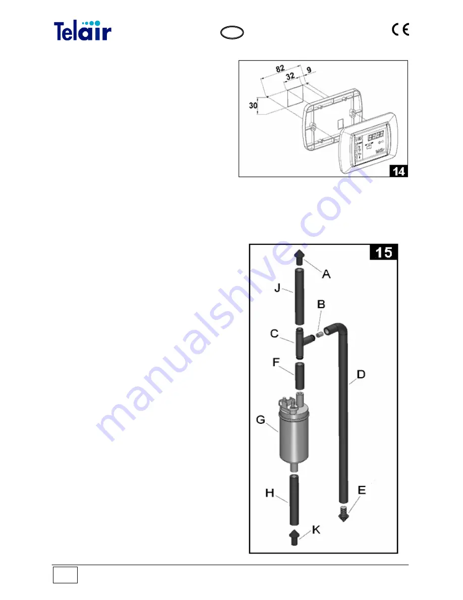
Choose your required position for the control
panel inside the vehicle and drill a 30 x 32 mm
rectangular hole. After letting out of the hole the
connecting cable coming from the generating set
(paragraph 4.6) connect the cable black
connector on the back of the electronic control
panel. Fix the electronic control panel (Fig.14) by
using 3 x 20 mm self-tapping screws, making
sure that the rear part does not interfere with
other surfaces. Apply light pressure to fix the
plastic frame, until the anchoring tabs click in.
4.8 Auxiliary (optional) fuel pump connection
If the distance that fuel must cover between the
fuel tank and the generating set is too long or the
tank is installed at a lower level than the
generating set, the fuel pump installed inside the
generating set may find it difficult to take fuel in
from the tank by suction. In this case, an auxiliary
optional fuel pump (code 00507) should be
installed as close as possible to the tank for easy
priming.
Summary of Contents for Energy 2510B
Page 29: ...Vers 001 Energy 2510 B 29 GB DRAWING FOR SPARE PARTS LIST ENERGY 2510 B ...
Page 30: ...Energy 2510 B Vers 001 30 GB ...
Page 31: ...Vers 001 Energy 2510 B 31 GB ...
Page 39: ...Vers 001 Energy 2510 B 39 GB Notes ...
Page 40: ......


