background image

TMM-100 

OPERATION


TEA 

TMM-100_User_Manual_r4.doc Rev4 

2-7


To cease operation of the TMM-100 software, click on the QUIT button at the lower right of 
the screen. The unit can be left connected (the front panel green indicator will remain on) to 
the computer but will be inactive until the TMM-100 program is again loaded and run. 


Exit Program 

To cease operation of the TMM-100 software, click on the QUIT button at the lower right of 
the screen. The unit can be left connected (the front panel green indicator will remain on) to 
the computer but will be inactive until the TMM-100 program is again loaded and run. 


Summary of Contents for TMM-100

Page 1: ...100 Temperature Measurement Module Operating Manual Thermal Engineering Associates Inc 3287 Kifer Road Santa Clara CA 95051 USA Tel 1 650 961 5900 Fax 1 650 227 3814 E mail info thermengr com Revisio...

Page 2: ...tion tasks is at the user s risk and responsibility 2019 by Thermal Engineering Associates Inc TEA Santa Clara CA USA All rights re served No part of this manual may be copied or otherwise reproduced...

Page 3: ...sing channels the internal precision IM current source provides 1 00mA with a voltage compliance of 2V The internal voltage meas urement circuit measures to 1 999V with 1mV resolution The temperature...

Page 4: ...hermocouple Number of Channels 2 Type T Range 0 to 199 C Resolution 0 1 C Accuracy 0 1 of fs 1 4 C Connector Front Panel Miniature Jack Omega NMP T or equivalent Temperature Measure Thermistor Number...

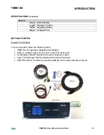
Page 5: ...ht 0 42Kg 14 7oz GETTING STARTED Unpack Your Module Your box should contain the following items TMM 100 Temperature Measurement Module USB 2 x Cable Type A on one end Type B on other end Combination D...

Page 6: ...panels Pay particular attention to the LEDs on the front panel Module Front Panel The TMM 100 front panel has Green Power LED Red LED for USB Tx Data Yellow LED for USB Rx Data 2 x 8 connector for Di...

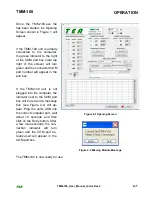
Page 7: ...OM port number will appear in the port box If the TMM 100 unit is not plugged into the computer the indicator next to the COM port box will be red and a message box see Figure 2 2 will ap pear Plug th...

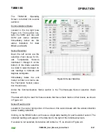
Page 8: ...degrees centigrade Immediately below the unit model number and name are the Thermistor Sensor selec tion check boxes Figure 2 3 Sensor Selection Under the Communications Status section is the Thermoc...

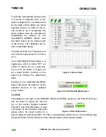
Page 9: ...either OFF as shown in Figure 2 4 as a grey but ton or ON as shown in Figure 2 5 as a green button Clicking on the button will change the operational state Figure 2 4 Sensor Read Clicking on the CONT...

Page 10: ...e up down arrow on the left of the data box The 10ms selection only works when a single sensor i e either Diode Thermistor or Thermocouple is selected The 100ms and 1s selections will work for any com...

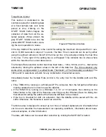
Page 11: ...seconds after starting the scan data will appear in the table on a row by row basis The last data collected is shown on the last line The top table in Figure 2 8 shows mV for each diode and C for the...

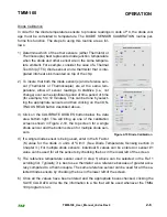
Page 12: ...n clicking on the CON TINOUS READ button described above 3 Click on the CALIBRATE DIODES button below the data area bottom right This will bring up one of the calibration screens shown in Figure 2 10...

Page 13: ...anel green indicator will remain on to the computer but will be inactive until the TMM 100 program is again loaded and run Exit Program To cease operation of the TMM 100 software click on the QUIT but...

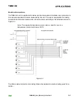
Page 14: ...unit The user is responsible for making the electrical connection between the unit and sensors according to the schematic shown in Figure 3 1 Note The supplied temperature sensor cable is rated for us...

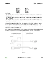
Page 15: ...anode connects to the second Brown conductor and cathode connects to second Red conductor The TMM 100 is designed to used 10K NTC Negative Temperature Coefficient thermis tors A surface mount device...

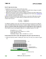
Page 16: ...urrent of 1mA for TEA s Thermal Test Chips are TTC 1001 0 5598 C mV TTC 1002 0 5046 C mV The TMM 100 supplies 1mA to each of the diodes connected and measures the voltage for each of the diodes select...

Page 17: ...until a steady state condition has occurred i e when the diode voltages stop changing to record the diode voltage and the Heat Sink temperature 7 Monitor the heat sink temperature until a steady stat...

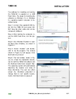
Page 18: ...rive into the sys tem Step 3 Use Windows Explorer to open the flash drive directory as shown in Figure 4 1 Step 4 Select Installer and double click to run the program The window shown in Figure 4 2 wi...

Page 19: ...boxes may appear showing installation progress Step 7 When the software installation is complete the final window see Figure 4 5 will appear Click Next button to pro ceed Figure 4 4 Step 8 With the in...

Page 20: ...100 Accessories TEA Diode Thermistor Cable Assembly TEA PN 985 00801 000 Thermocouples TEA PN 680 00002 001 Type T 36 gauge 3 feet long Omega Engineering SC TT T 36 36 TMM 100_User_Manual_r4 doc Rev3...

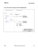
Page 21: ...TMM 100 Accessories TEA Fan Control Cable Assembly TEA PN 985 00802 000 TMM 100_User_Manual_r4 doc Rev3 5 2...

Page 22: ...ll be charged to the customer according to TEA s normal rate and billing procedures All returns must be author ized in writing by TEA prior to being returned No other warranty expressed or implied acc...

Page 23: ...uct via shipping costs collect or be billed by TEA for the return shipping costs See shipping instructions below 4 A description of the problem with the TEA product must be provided with the returned...

Page 24: ...e date the customer s property reaches TEA until it is shipped from TEA Transportation time in both directions is additional The fifteen working day period is subject to manufac turing schedules at TE...

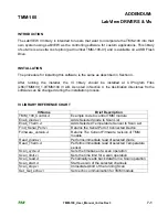
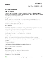
Page 25: ...be changed during the installation process VI LIBRARY REFERENCE CHART VI Name Brief Description TMM_100_Control vi Example code to control TMM module Enab_diode vi Adds Selected diode to Scan List Ena...

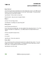
Page 26: ...vi This adds the Thermistors channels 1 2 and or the thermocouples channels 3 4 to the scan list Use this function to remove the sensors from the list also Input Numeric Thermal sensor number 0 3 Inp...

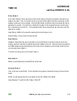
Page 27: ...Boolean True Relay ON False Relay OFF Scan_Cycle vi Scan Cycle can be set from 0 2 Scan_Cycle sets the sampling rate Set this variable before calling Scan_Start vi The 10ms setting is only valid for...

Page 28: ...ut in a table Input String Buffer to be used for parsing the rows during a scan Output String Chars read at the serial port Scan Start vi Initiates a Scan that has previously been set up with the Scan...

Reviews: