background image

– 3 –

Before Use

Read This Before Operating

IMPORTANT (for U.K. Customers)

DO NOT cut off the mains plug from this
equipment.

If the plug fitted is not

suitable for the power points in your
home or the cable is too short to reach
a power point, then obtain an
appropriate safety approved extension
lead or consult your dealer.

If nonetheless the mains plug is cut   off,
remove the fuse and dispose of   the
plug  immediately, to avoid a possible
shock hazard by inadvertent
connection to the mains supply.

If this product is not provided with a
mains plug, or one has to be fitted, then
follow the instructions given below:

IMPORTANT.

The wires in this mains

lead are coloured in accordance with
the following code:

GREEN-AND-YELLOW: EARTH
BLUE:

NEUTRAL

BROWN:

LIVE

WARNING:

This apparatus must be

earthed.

As the colours of the wires in the mains
lead of this apparatus may not
correspond with the coloured markings
identifying the terminals in your plug
proceed as follows.

The wire which is coloured GREEN-
and-YELLOW must be connected to  the
terminal in the plug which is marked by
the letter E or by the safety              earth
symbol 

©

or coloured GREEN or

GREEN-and-YELLOW.

The wire which is coloured BLUE must
be connected to the terminal which is
marked with the letter N or coloured
BLACK.

The wire which is coloured BROWN
must be connected to the terminal
which is marked with the letter L or
coloured RED.

When replacing the fuse only a
correctly rated approved type should
be used and be sure to re-fit the fuse
cover.

IF IN DOUBT — CONSULT A
COMPETENT ELECTRICIAN.

Place the amplifier on a hard flat
surface.

The ventilation holes should not be
covered. Make sure there is at least 20
cm (8 inches) of space above and at
least 5 cm (2 inches) of space besides
the amplifier. Do not place CD player or
other equipment on top of the amplifier.

Avoid placing it in direct sunlight or
close to a source of heat. Also avoid
locations subject to vibrations and
excessive dust, heat, cold or moisture. 

Do not open the cabinet, as this might
result in circuitry damage or electrical
shock.

When removing the power plug from the
wall outlet, always pull directly on the
plug; never yank the cord.

Do not attempt to clean the unit with
chemical solvents, as this might damage
the finish. Use a clean, dry cloth.

Keep this manual in a safe place for
future reference.

Notes on Power Sources

Plug the AC power cord into an AC wall
receptacle. The correct voltage for
operating your unit is printed on the rear
panel.

Main POWER Switch

The main POWER switch is located on
the rear of the unit.

Press the ON side of this rocker (seesaw)
switch to turn power ON (standby position);
press the OFF side to turn power off.
Whenever the power is ON, the indicator on
the front panel glows red. 

Note:

Leave this main power switch ON at

all times.

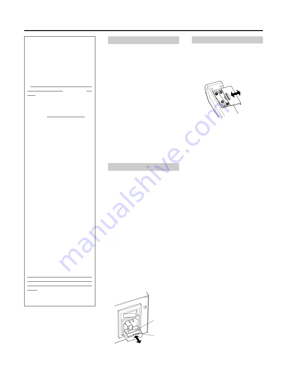
AC IN Socket

Plug the provided AC power cord into this
socket.

Fuse Holder

After replacing fuses, be sure to close the
fuse compartment until it clicks.

When operating the remote control unit,
point it towards the remote sensor on the
front panel of the unit.

Battery Installation

Remote Control Unit

1. Remove the battery compartment

cover.

2. Insert two “AAA” (R03, UM-4) dry

batteries.

Make sure that the batteries are
inserted with their positive 

±

and

negative 

poles positioned correctly.

3. Close the cover until it clicks.

Battery Replacement.

If you notice that the distance between
the remote control unit and the player for
correct operation becomes shorter, it
indicates that the batteries are exhaust-
ed. In this case replace the batteries with
new ones.

Precautions concerning batteries

Be sure to insert the batteries with
correct positive 

±

and negative 

polarities.

Use batteries of the same type. Never
use different types of batteries
together.

Rechargeable and non-rechargeable
batteries can be used. Refer to the
precautions on their labels.

When the remote control unit is not to
be used for a long time (more than a
month), remove the batteries from the
remote control unit to prevent them
from leaking. If they leak, wipe away
the liquid inside the battery
compartment and replace the batteries
with new ones. 

Do not heat or disassemble batteries
and never dispose of old batteries by
throwing them in fire.

Main fuse

Spare fuse

Summary of Contents for A-BX10 MK II

Page 1: ...fier OWNER S MANUAL 3 MANUEL DU PROPRIETAIRE 6 BEDIENUNGSANLEITUNG 9 MANUALE DI ISTRUZIONI 12 MANUAL DEL USUARIO 15 GEBRUIKSAANWIJZING 18 9A07108800 This appliance has a serial number located on the rear panel Please record the model number and serial number and retain them for your records Model number Serial number WARNING TO PREVENT FIRE OR SHOCK HAZARD DO NOT EXPOSE THIS APPLIANCE TO RAIN OR M...

Page 2: ... of the mast and supporting structure grounding of the lead in wire to an antenna discharge unit size of grounding conductors location of antenna discharge unit connection to grounding electrodes and requirements for the grounding electrode Note to CATV system installer This reminder is provided to call the CATV system installer s attention to Section 820 40 of the NEC which provides guidelines fo...

Page 3: ...t result in circuitry damage or electrical shock When removing the power plug from the wall outlet always pull directly on the plug never yank the cord Do not attempt to clean the unit with chemical solvents as this might damage the finish Use a clean dry cloth Keep this manual in a safe place for future reference Notes on Power Sources Plug the AC power cord into an AC wall receptacle The correct...

Page 4: ...have the same reference numbers The power is turned on off standby by pressing the power button on the remote control unit in standby mode 7muting button on the remote control unit Press this to mute 0 dB the sound from the speakers when answering the telephone etc To restore the original volume press the input selector buttons or level control buttons While muting is engaged the volume level disp...

Page 5: ...EC jacks rAC IN Socket See page 3 tMain POWER Switch See page 3 Press the ON side of this rocker seesaw switch to turn power ON standby position Note Leave this main power switch ON at all times yFuse Holder See page 3 Tape Dubbing You can dub from the deck connected to TAPE 1 jacks to the deck connected to TAPE 2 jacks Dubbing from TAPE 2 deck to TAPE 1 deck is not possible 1 Set the playback dec...

Page 6: ...tion Quand l alimentation est fournie l indicateur sur le panneau avant s allume en rouge Remarque Toujours laisser cet inter rupteur principal d alimentation sur ON Prise d entrée secteur Brancher le cordon d alimentation secteur fourni dans cette prise Porte fusible Après remplacement des fusibles s assurer de refermer le compartiment fusible jusqu à son déclic Fusible principal Fusible de recha...

Page 7: ...r sur la télécommande en mode d attente 7Touche muting sur la télécommande La presser pour rendre silencieux 0 dB le son des haut parleurs pour répondre au téléphone etc Pour revenir au volume original appuyer sur les touches du sélecteur d entrée ou sur les touches de commande de niveau Alors que le silencieux est engagé l affichage du niveau sonore montre 0 dB 8Touche de contrôle de la balance C...

Page 8: ... voir page 6 tInterrupteur principal d alimenta tion POWER voir page 6 Appuyer sur le côté ON de ce com mutateur à bascule pour mettre l alimentation sur marche position d attente Remarque Toujours laisser cet inter rupteur principal d alimentation sur ON yPorte fusible voir page 6 Copie de bande Vous pouvez copier de la platine raccordée aux prises TAPE 1 vers la platine raccordée aux prises TAPE...

Page 9: ...nd eine neue Batterie verwenden O Sowohl Einweg als auch wiederauf ladbare Batterien sind verwendbar Die Sicherheitshinweise auf den Batterien beachten O Bei längerem Nichtgebrauch über einen Monat sollten die Batterien entnommen werden um dem Auslaufen der Batterien vorzubeugen Ausgelaufene Batterien entnehmen und nach Säubern des Batteriefachs gegen frische auswechseln O Batterien niemals erhitz...

Page 10: ...bedieneinheit Taste power muß das Gerät auf Bereitschaft geschaltet sein 7Stummschalt Taste muting auf Fernbedienung Während eines Telefongespräches etc kann durch Betätigen dieser Taste die Wiedergabe Lautsprecher stumm geschaltet 0 dB werden Zur Rückstellung auf die urspüngliche Lautstärke die Eingangswahltasten oder Pegeltasten verwenden Bei Stummschaltung liegt die Lautstärkeanzeige 0 dB vor 8...

Page 11: ...ter POWER Siehe Seite 9 Zur Einschaltung der Betriebsbereitschaft diesen Wippschalter im Abschnitt ON Bereitschaft drücken Hinweis Der Netz Hauptschalter muß stets auf ON gestellt sein ySicherungsfach Siehe Seite 9 Bandkopieren Bandkopieren ist von Bandgerät 1 TAPE 1 Buchsen auf Bandgerät 2 TAPE 2 MONITOR Buchsen möglich Kopierbetrieb in Gegenrichtung ist nicht möglich 1 Das Wiedergabegerät TAPE 1...

Page 12: ...iviene rosso Nota Lasciace questo interruttore di corrente principale su la posizione attivata ON Presa AC IN Collegare qui il cavo di alimentazione a corrente alternata in dotazione Portafusibili Sostituiti i diffusori spingere il coperchio del vano fusibili sino a che non si chiude con uno scatto Fusibile principale Il telecomando deve essere usato puntandolo verso il sensore del pannello anteri...

Page 13: ...ndo sull apposito tasto power del telecomando 7Tasto muting sul telecomando Premere questo tasto per escludere 0 dB temporaneamente il suono dai diffusori quando si deve rispondere al telefono o in altre situazioni analoghe Per tornare al volume iniziale agire sui tasti di selezione dell ingresso o sui tasti di regolazione del livello In modalità di silenziamento il livello del volume visualizzato...

Page 14: ...di corrente principale POWER vedere a pag 12 Premete il lato ON dell interruttore per accendere l unità posizione di attesa Nota Lasciace questo interruttore di corrente principale su la posizione attivata ON yPortafusibili vedere a pag 12 Duplicazione di cassette Potete duplicare una cassetta dal registratore collegato alle prese TAPE 1 a quello collegato alle prese TAPE 2 La duplicazione in dire...

Page 15: ...ertar las pilas con sus polaridades positiva y negativa correctas O Utilice el mismo tipo de pilas Nunca utilice diferentes tipos de pilas juntas O Pueden utilizarse pilas recargables y no recargables Refiérase a las precauciones en sus rótulos O Si no va a utilizar el control remoto por mucho tiempo más de un mes retire las pilas para evitar pérdidas Si se producen pérdidas limpie el líquido en e...

Page 16: ...ectar conectar espera la alimentación presione el botón power en el control remoto en el modo de espera 7Botón muting en el control remoto Presiónelo para silenciar 0 dB el sonido proveniente de los altavoces cuando responda al teléfono etc Para restablecer el volumen original presione los botones selectores de entrada o los botones de control de nivel Mientras el silenciador está activado el moni...

Page 17: ... magnetófono a los jacks REC rEnchufe AC IN ver página 15 tInterruptor principal POWER ver página 15 Presione el lado ON de este interruptor basculante vaivén para conectar la alimentación ON posición de espera Nota Deje este interruptor principal de alimentación en ON yPortafusible ver página 15 Copia de cintas Usted puede copiar desde la platina conectada a los jacks TAPE 1 a la platina conectad...

Page 18: ...droge doek Bewaar deze gebruiksaanwijzing op een vilige plaats om deze later te kunnen naslaan Betreffende de stroomvoorziening Opmerking Laat deze spannings schakelaar ingeschakeld ON AC IN netuitgang Steek het bijgeleverde netsnoer in deze uitgang Zekeringhouder Vergeet de zekeringhouder na het wisselen van zekeringen niet te sluiten De zekeringhouder dient vast te klikken Hoofdzekering Reservez...

Page 19: ...ktro statische luidsprekers qGebalanceerde ingangsaansluiting De gebalanceerde ingang wordt met XLR stekkers verbonden overeenkomstig de IEC specificaties PIN 1 GND aarde PIN 2 PIN 3 wAardaansluiting GND Sluit de aarddraad van de draaitafel aan op deze aansluiting eAudiosignaalaansluitingen Ingangsaansluitingen AUX Sluit de uitgangsaansluitingen van een videorecorder op deze aansluitingen aan Kopi...

Page 20: ...t dit aan dat de batterijen uitgeput zijn Vervang de batterijen in dit geval door nieuwe Technische gegevens Continue uitgangsvermogen RMS 100W 100W 20 20 000 Hz 8 ohm 160W 160W 20 20 000 Hz 4 ohm Dynamische uitgangsvermogen EIA 120W 120W 8 ohm 220W 220W 4 ohm Totale Harmonische vervorming continue uitgangsvermogen 0 04 20 20 000 Hz 6 dB 8 ohm 0 06 20 20 000 Hz 6 dB 4 ohm Ingangsgevoeligheid Imped...

Reviews: